
How to Build the Robotic Eyes Kit
Step-by-step photo guide to assembling the Greene Robotics animatronic Robotic Eyes Kit — an Arduino-powered DIY robotics project for beginners. No experience needed.
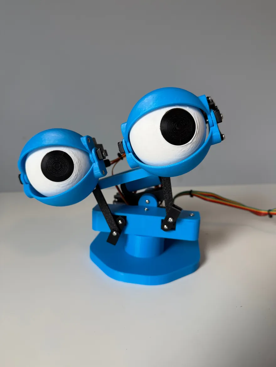
Introduction
Welcome to the official Greene Robotics tutorial for the Robotic Eyes Kit! This step-by-step guide walks you through assembling and bringing to life your own animatronic eyes — just like the ones in our product photos and videos.
This tutorial pairs with the Robotic Eyes Kit, available on our Etsy shop. Every part you need is included — servos, control board, 3D-printed pieces, and wiring — so you can focus on learning, building, and having fun.
Whether you’re a beginner or an experienced maker, this project is approachable and easy to follow. By the end, you’ll have a fully functional pair of animatronic eyes ready to control. Let’s dive in!
Credit & inspiration
Before we begin, we want to give credit where it’s due. This project is inspired by an original design by James Bruton, a talented YouTuber with 1.38 million subscribers at the time of writing. Check out his channel at https://www.youtube.com/@jamesbruton. The project is based on his video, ‘How To Make Robots Move Smoothly | Arduino Tutorial.’ James released the CAD files and code under the MIT license, which permits use, modification, and distribution for commercial purposes, provided the original creator and license are acknowledged. While our project draws inspiration from his, we’ve significantly modified it to be more accessible to makers. Unlike James’s version, which uses various screw types and complex electronics, our kit uses a single M3 screw type and simplified circuitry, making it beginner-friendly and available as a complete kit. We extend a huge thank you to James Bruton for his inspiring open-source project and all the amazing content on his channel!
Our policy
Our number one goal is for you to finish this tutorial with a fully working robot. If any parts arrived damaged or broken, message us on Etsy and we’ll send replacements. However, once your build is fully functional, we’re no longer able to provide support for anything that happens after that point — including modifications, code changes, or anything else beyond the original kit.
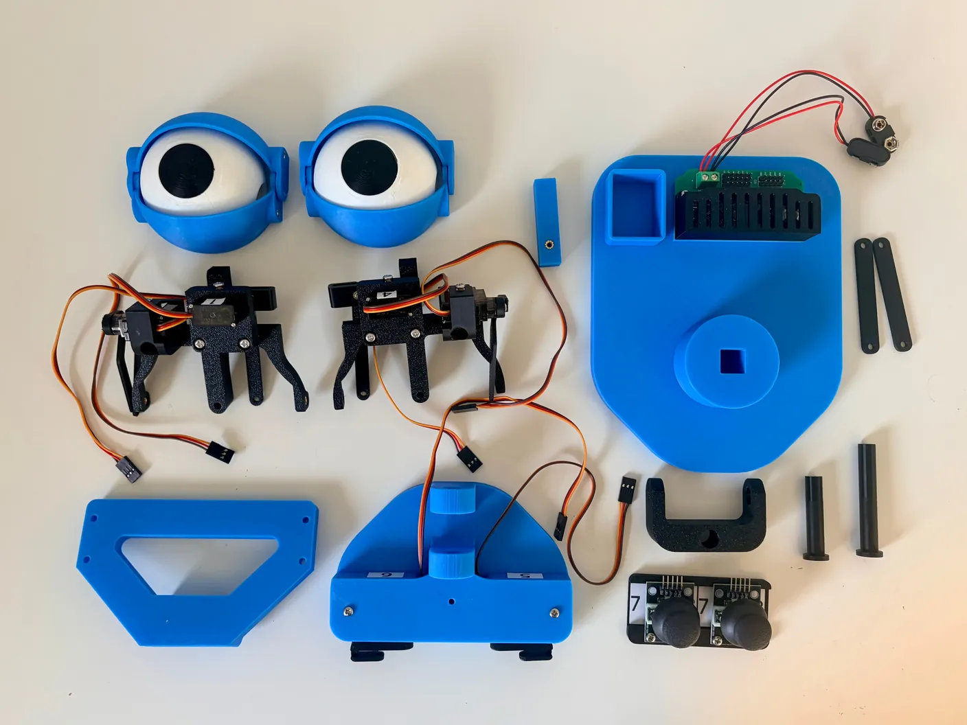
Before you start, please read through all of the instructions. We know reading can be boring, but skipping steps is one of the most common reasons a build goes wrong. Taking the time to read everything will help your robot work right the first time. Have fun!
Tip: All images can be clicked on to be enlarged, so that you can zoom in to get a closer look.
Assemble the Eyes
Start with the eyes. Grab an eye and the black part with the numbers 3 and 4 on the back, shown below.
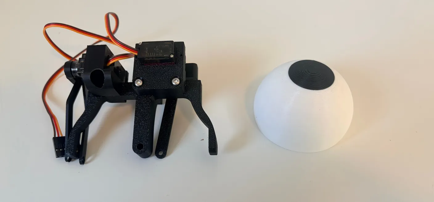
Note — pre-installed screws
Notice that there are some screws already installed on the mechanism. Do not touch these screws (tighten or loosen) — they come set the way they’re supposed to be. It may look like the screws holding the servos in are loose, but that’s on purpose. If they’re too tight, they could damage the servo, so leave them as they are.
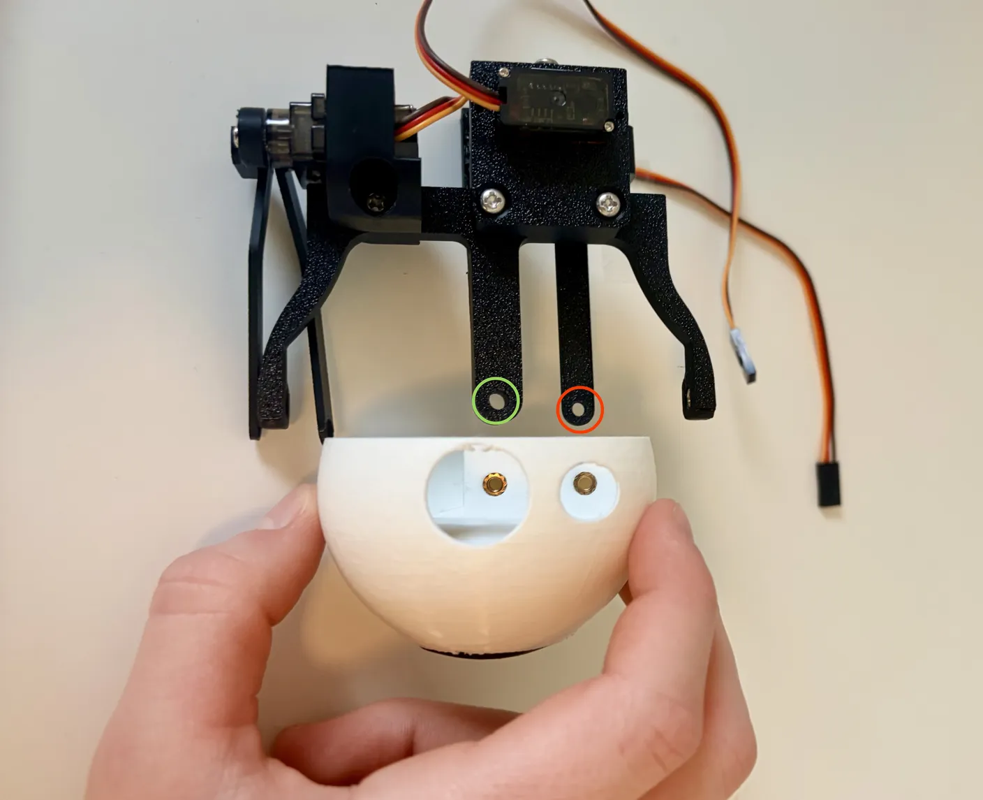
The two eyes are different — use the one that lines up with the two holes, as shown. Attach it to the mechanism with screws: the middle hole (circled green) takes a 16mm screw, the other hole (circled red) takes a 6mm screw.
Important!
Never move the servos by hand
Never manually move a servo motor by hand, at any point in the build. Servos are geared internally, and forcing them by hand can strip or break those gears. Only let the servo move on its own, under power.
It should look like the image below. Keep the screws snug but not overtight — if a screw is too tight, the friction will stop the eye from moving. It’s better to start them off loose, then tighten once you know it works.
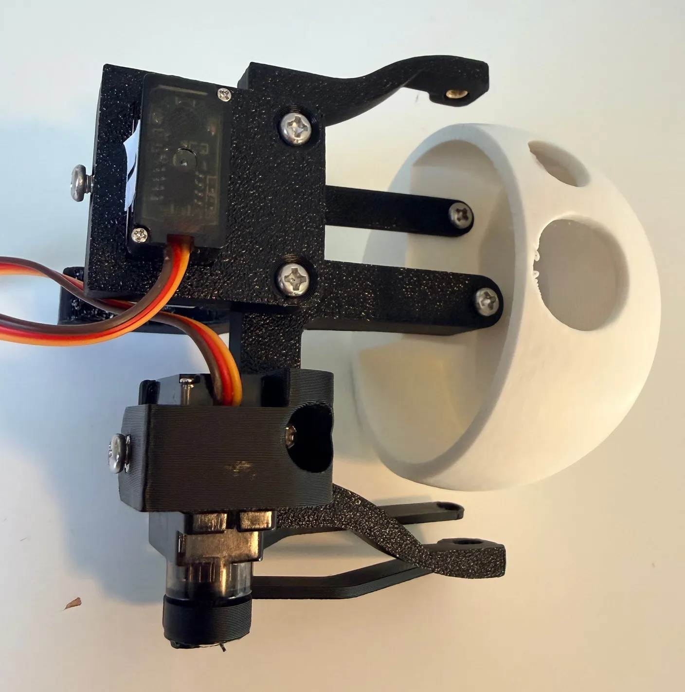
1× 16mm screw + 1× 6mm screw
Start two 12mm screws into the holes on the outside of the assembly, as shown. Don’t tighten them yet — just get them started.
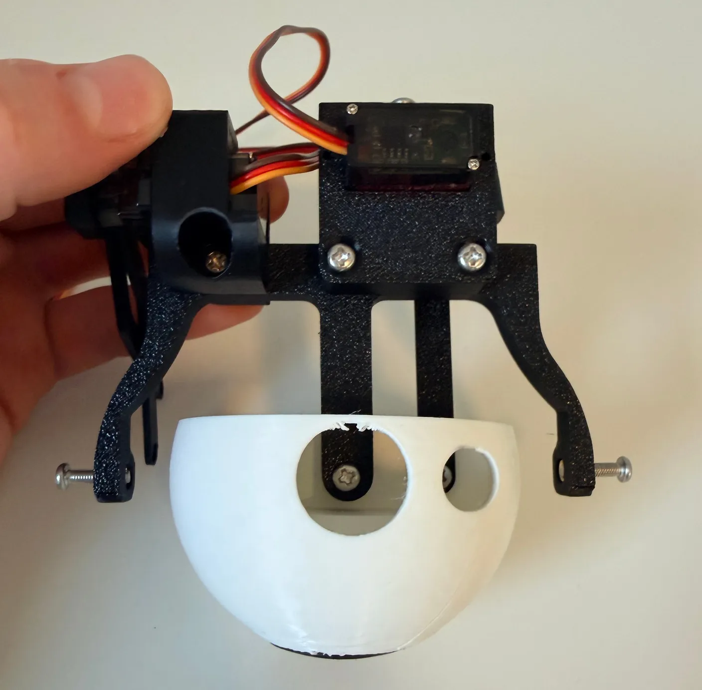
2× 12mm screws
Get a pair of eyelids and lay them flat, like this.
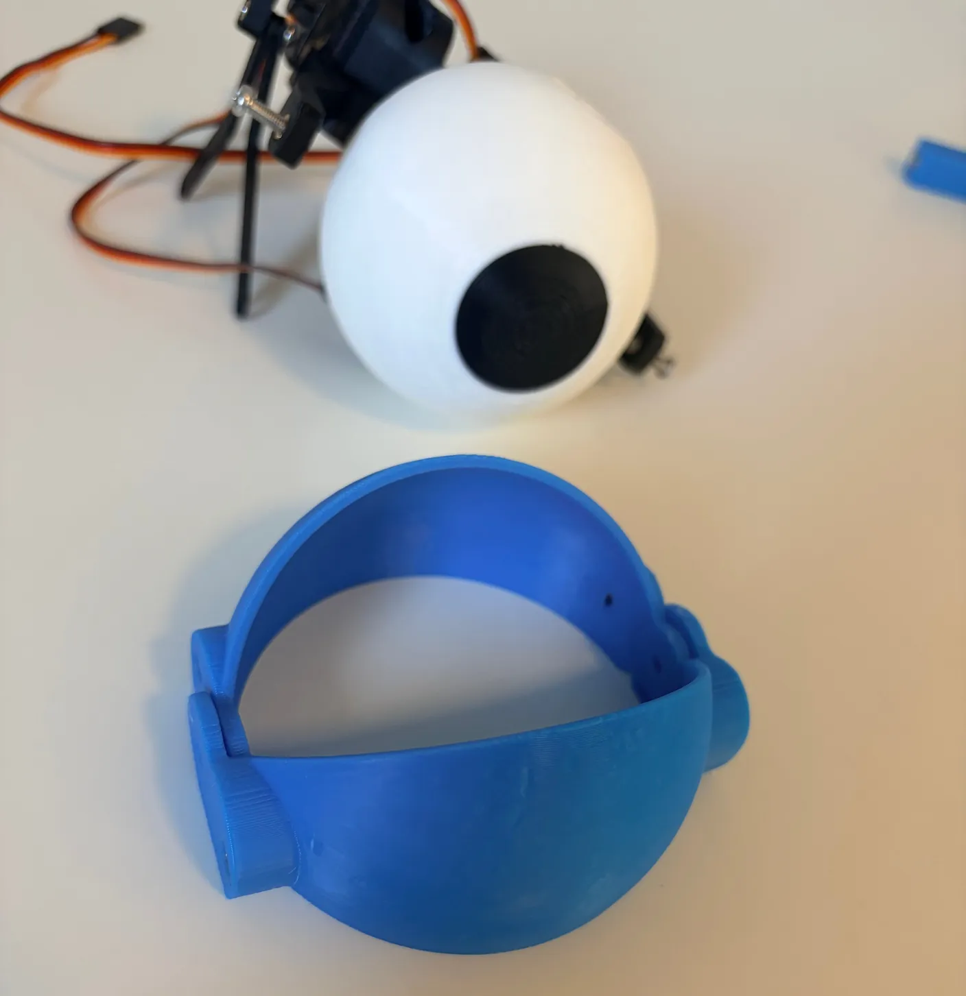
Lift them into the position shown. The center holes line up with the screws you just started, so you can tighten those fully to hold the eyelids in place.
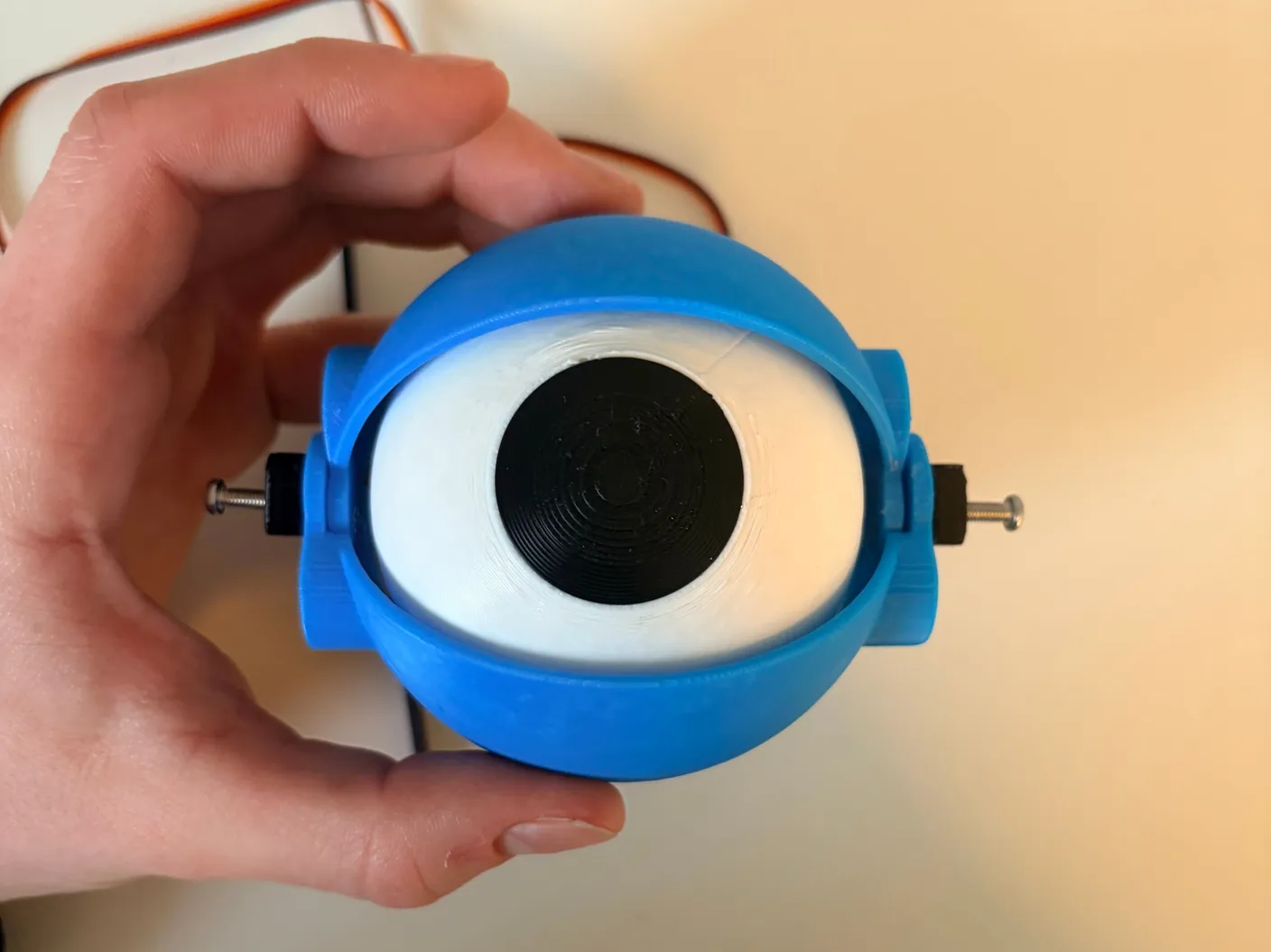
Once tightened, the screws hold the eyelids in place while still letting them move freely.
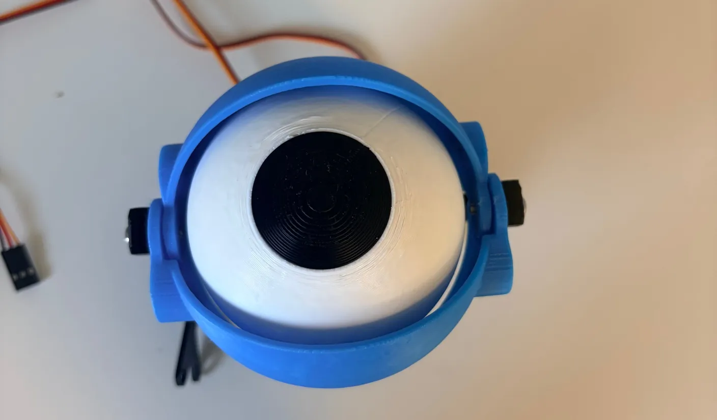
Connect the push rods to the eyelids with two 6mm screws, as shown. Remember, they should just be tight enough to keep the screw in place. If you make them too tight, it will restrict the eyelid from actually closing, which is a problem in itself, and it can also cause your motor to break. So, start loose, then once you know it works you can tighten them slightly if you’d like.
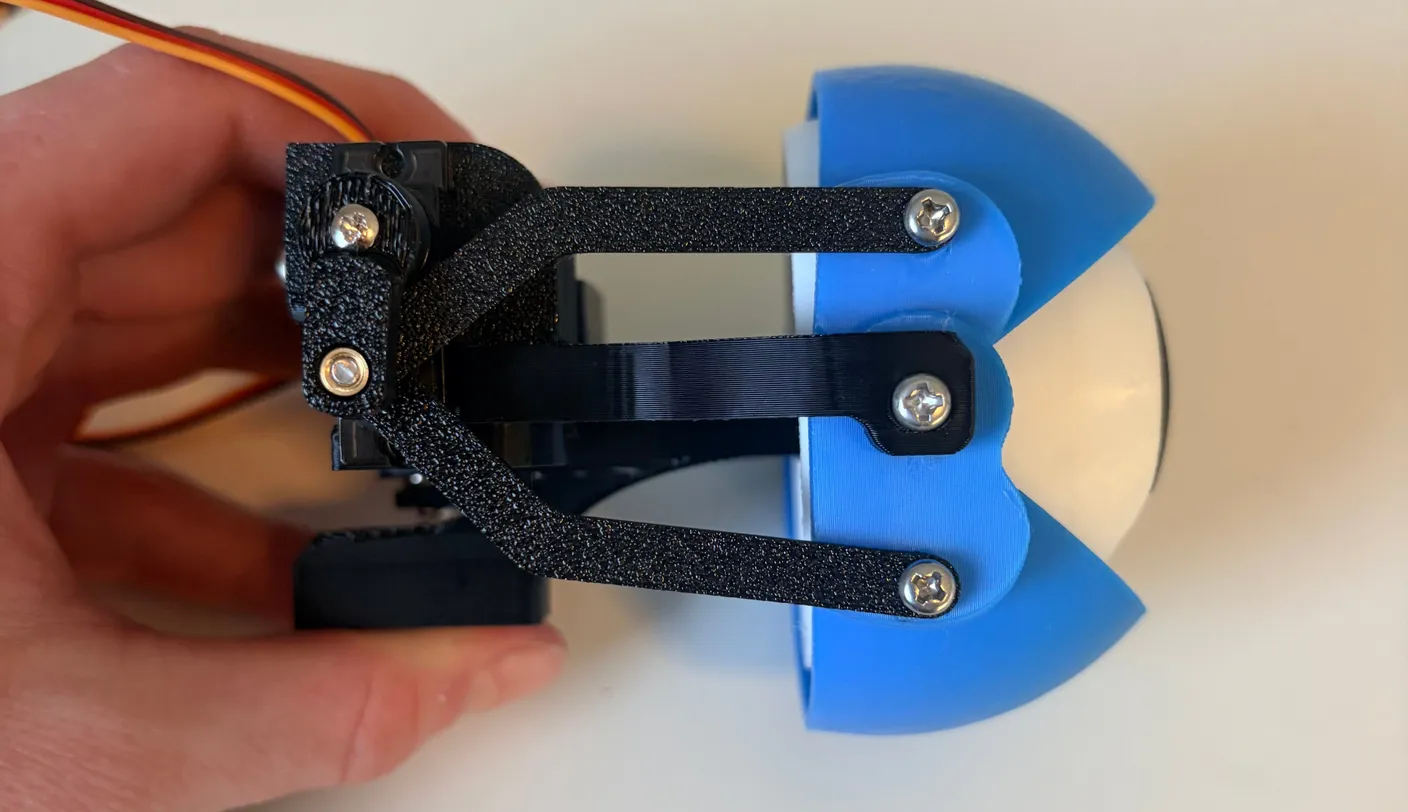
2× 6mm screws
Nice work — that’s one finished eye! Now build the second one (unless you’re going for a cyclops). The steps are identical, just mirrored, so reference the first eye as you go.
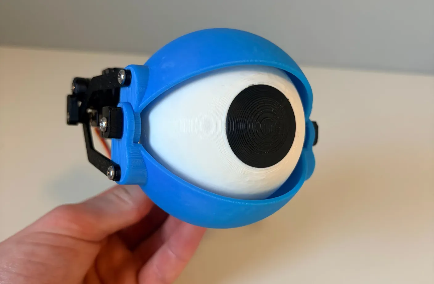
Assemble the Neck
With both eyes done, it’s time to attach them to the neck — the part that moves up, down, left, and right. Grab the piece shown below.
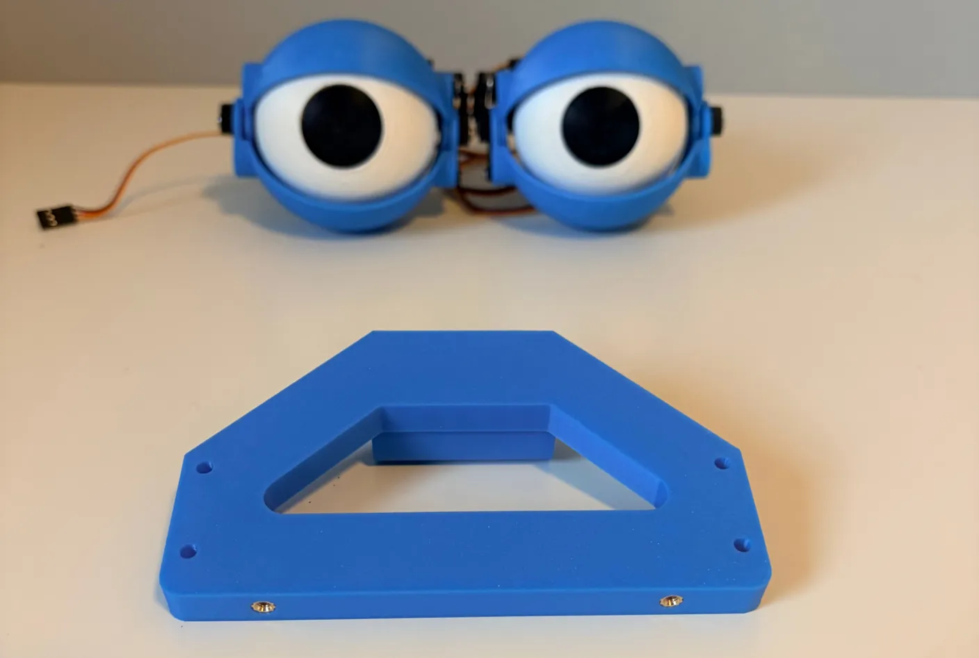
Flip the eyes upside down and arrange them exactly as shown, with the eyelid push rods facing outward.
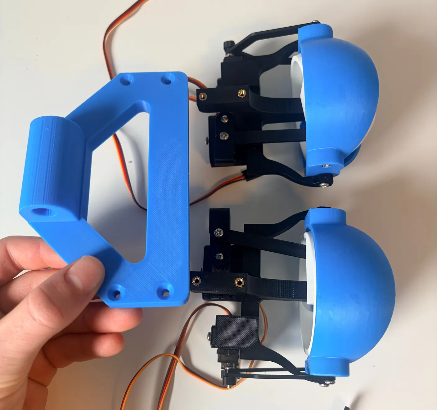
Once in place, use four 12mm screws to tightly secure the eye mechanism to the neck base.
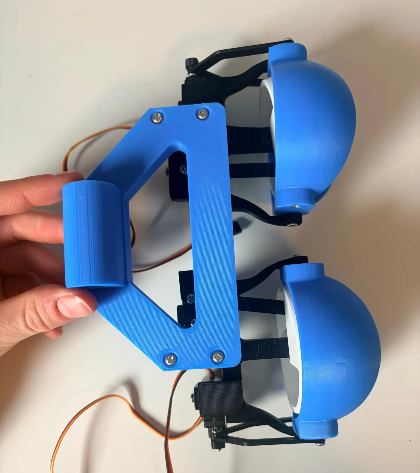
4× 12mm screws
Place the assembly as shown. The motors should read 1 to 4, left to right — if the leftmost motor is 3, swap the eyes’ positions. Match the image exactly, with the eyelid push rods on the outside.
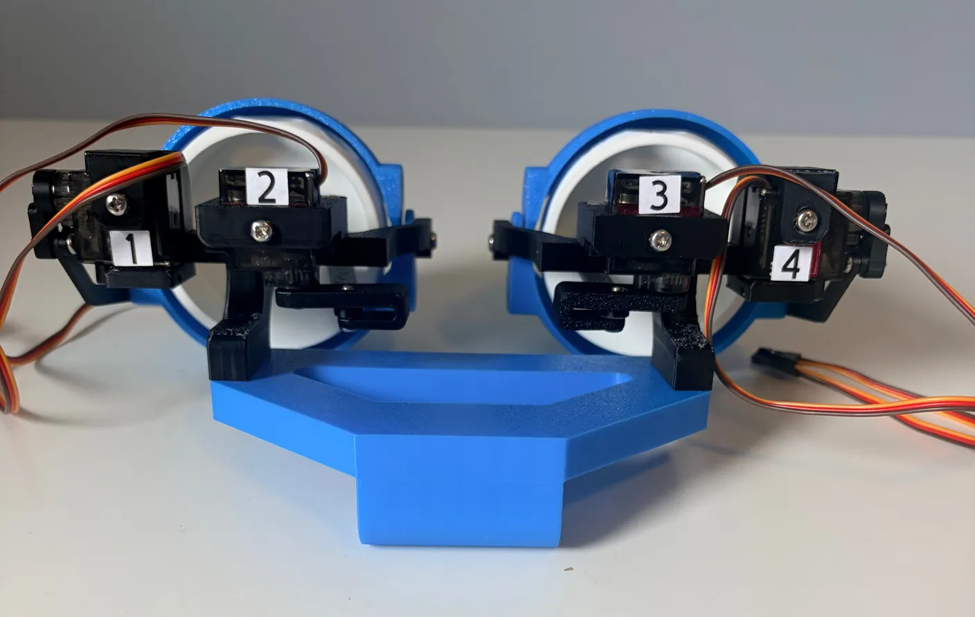
Next, we will connect the platform that holds the eyes to the “neck” that moves it up, down, left, and right. Gather the parts shown below.
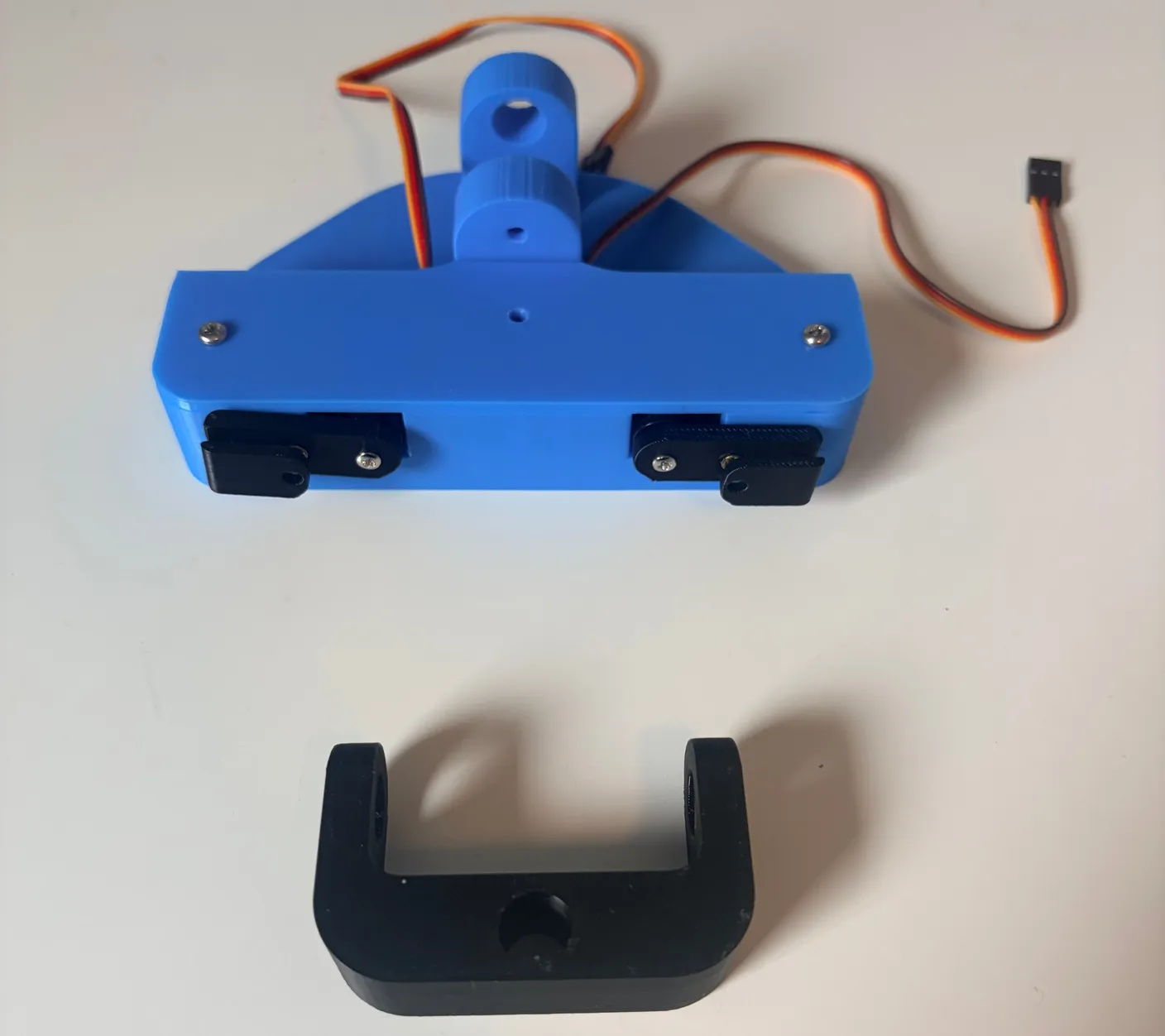
Set the black joint into the base as shown. Then take the smaller of the two black pins and push it all the way through the hole to secure the joint.
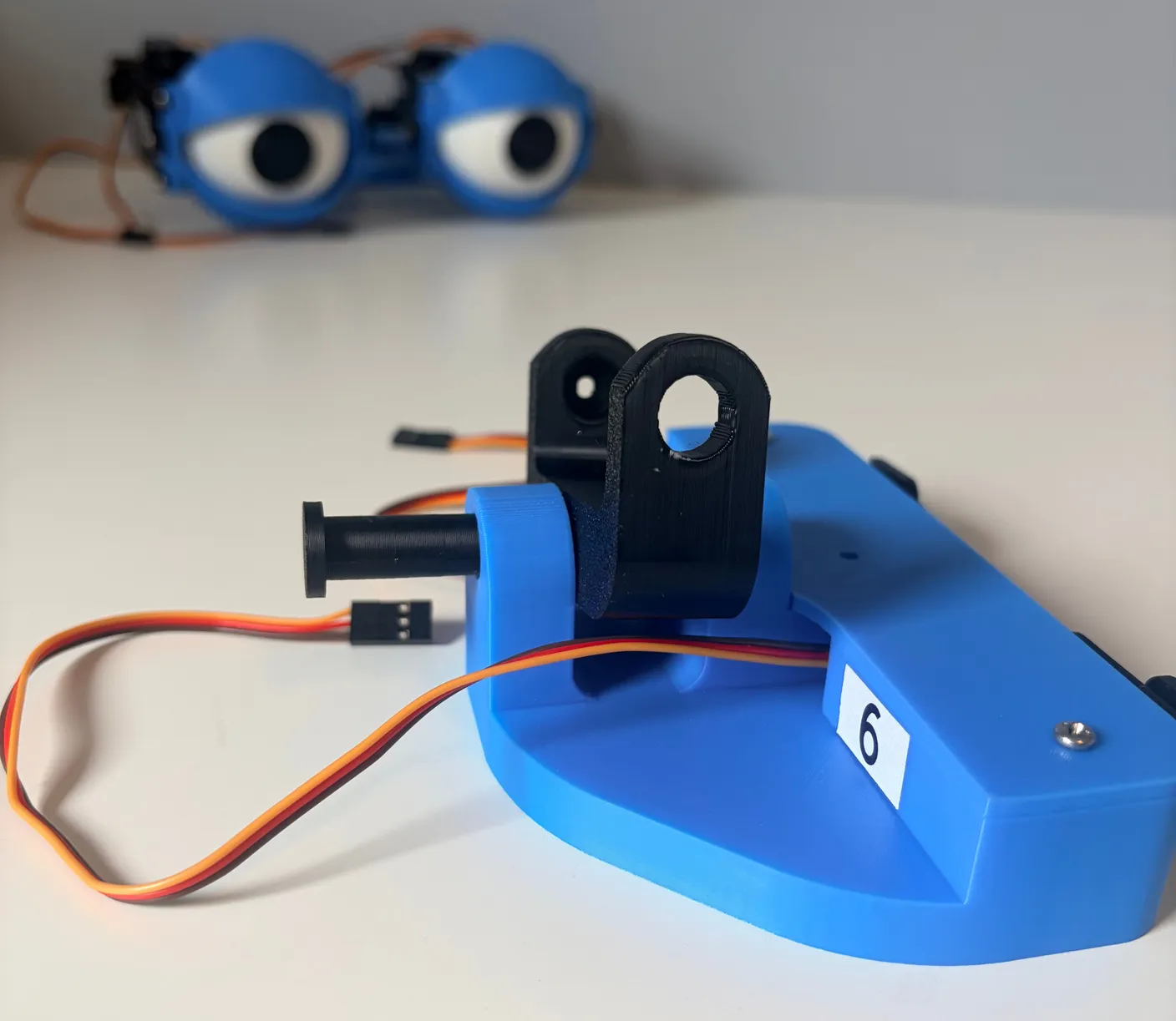
Secure it with a 6mm screw on the other side.
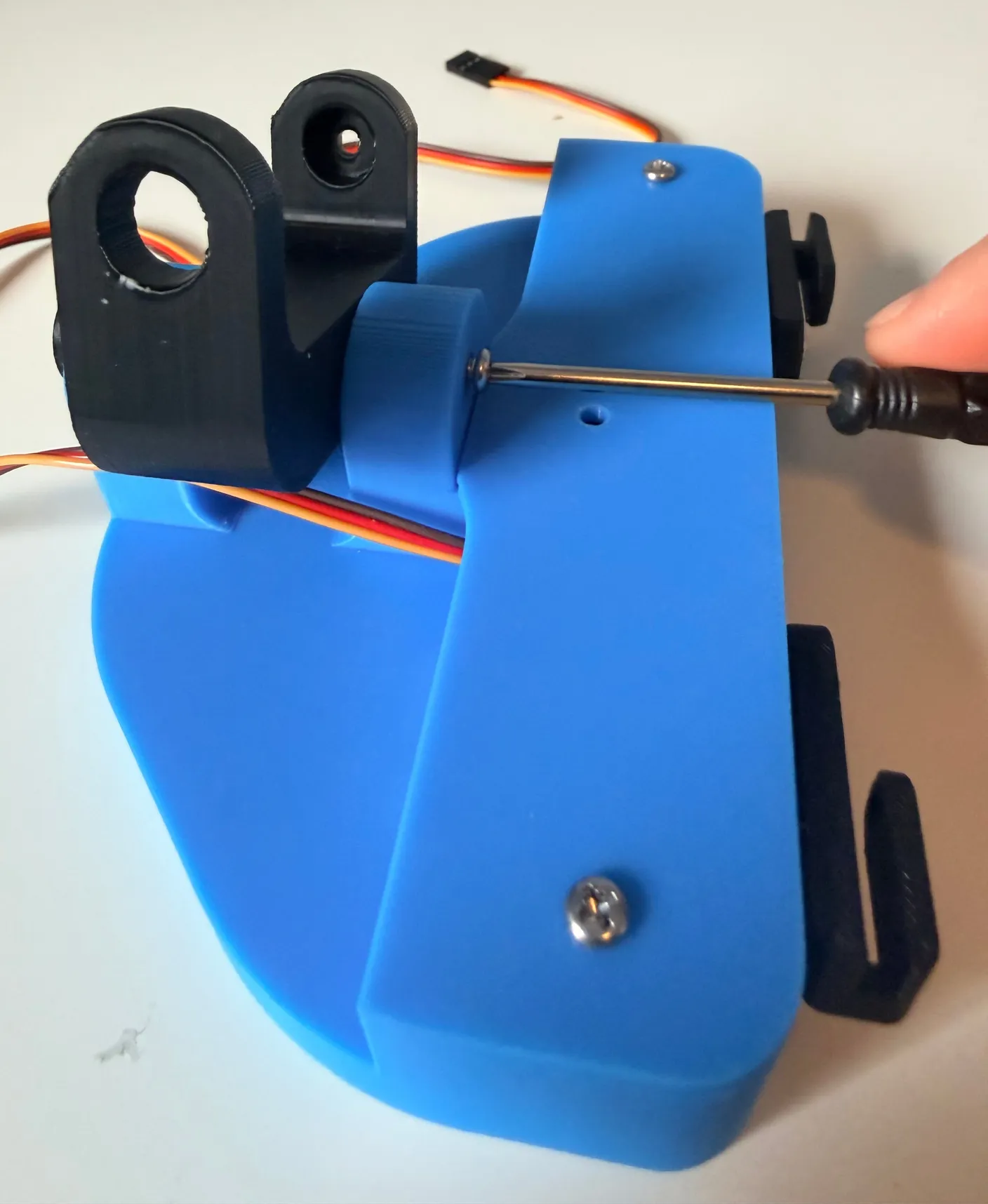
1× 6mm screw
Assembled, it should look like the image below, and the black joint should rotate easily.
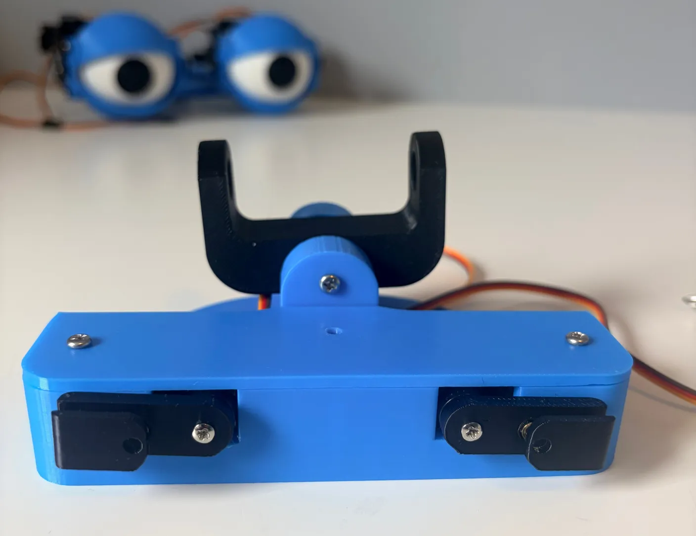
Get the two black rods — these push the eyes up and down for neck movement. Attach them to the servo motors by aligning the hole on each rod with the hole on the motor.
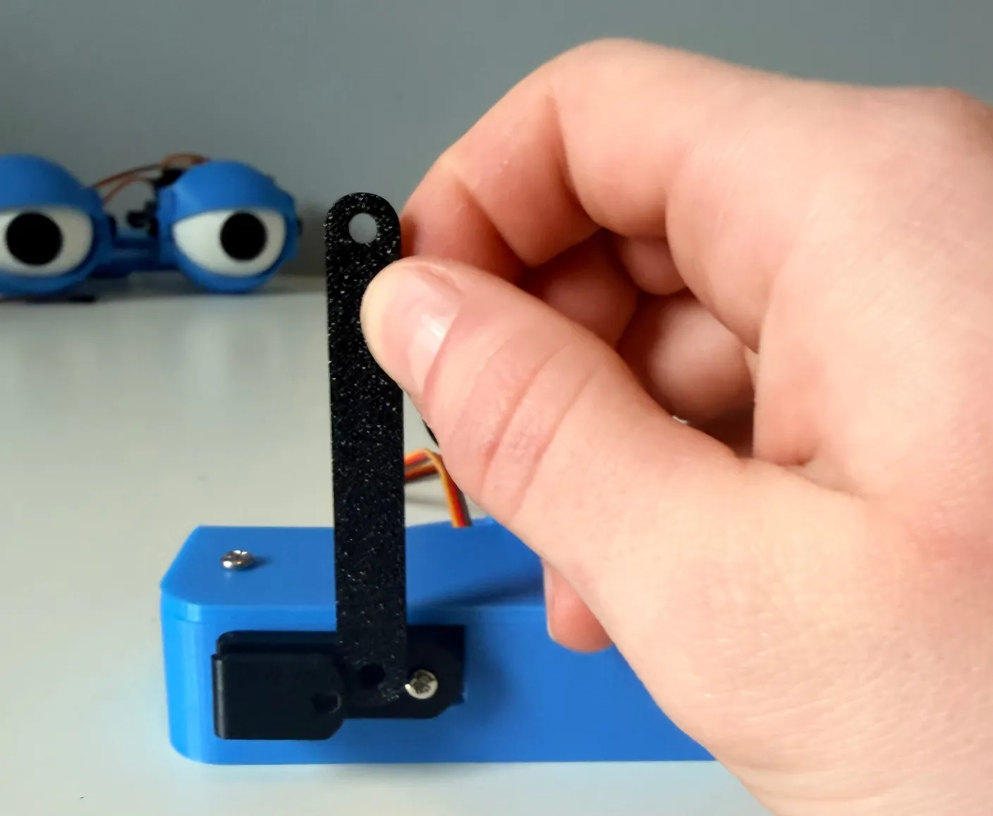
Secure them with two 10mm screws — snug, but not too tight.
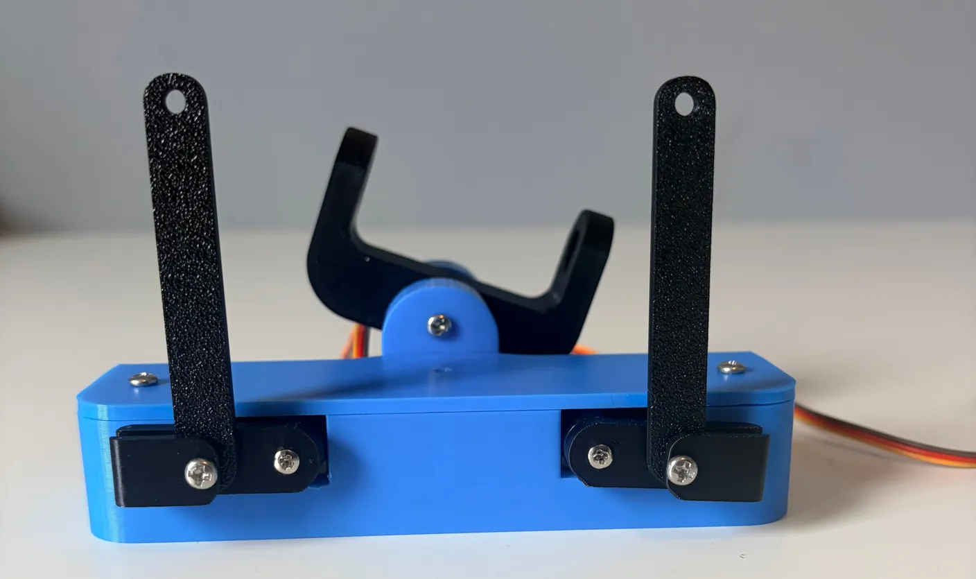
2× 10mm screws
Now attach the assembled eyes: align the hole on the bottom of the eye base with the black neck joint you installed earlier.
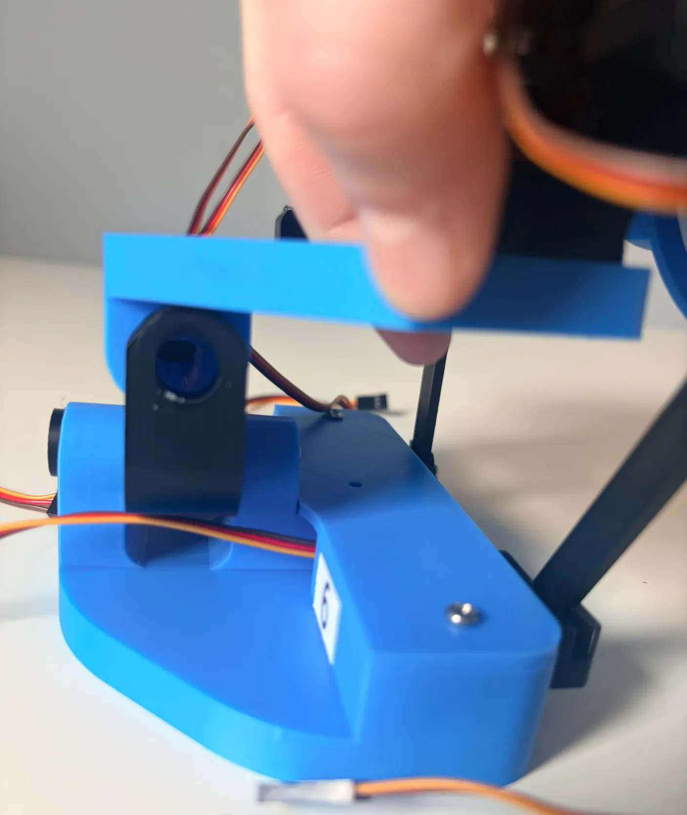
Connect the joint with the long pin, sliding it all the way through.
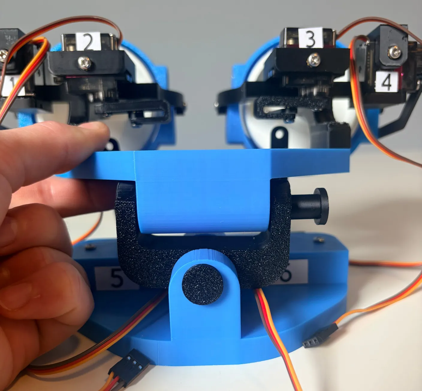
Secure the pin with a 6mm screw so it can’t fall out, as shown.
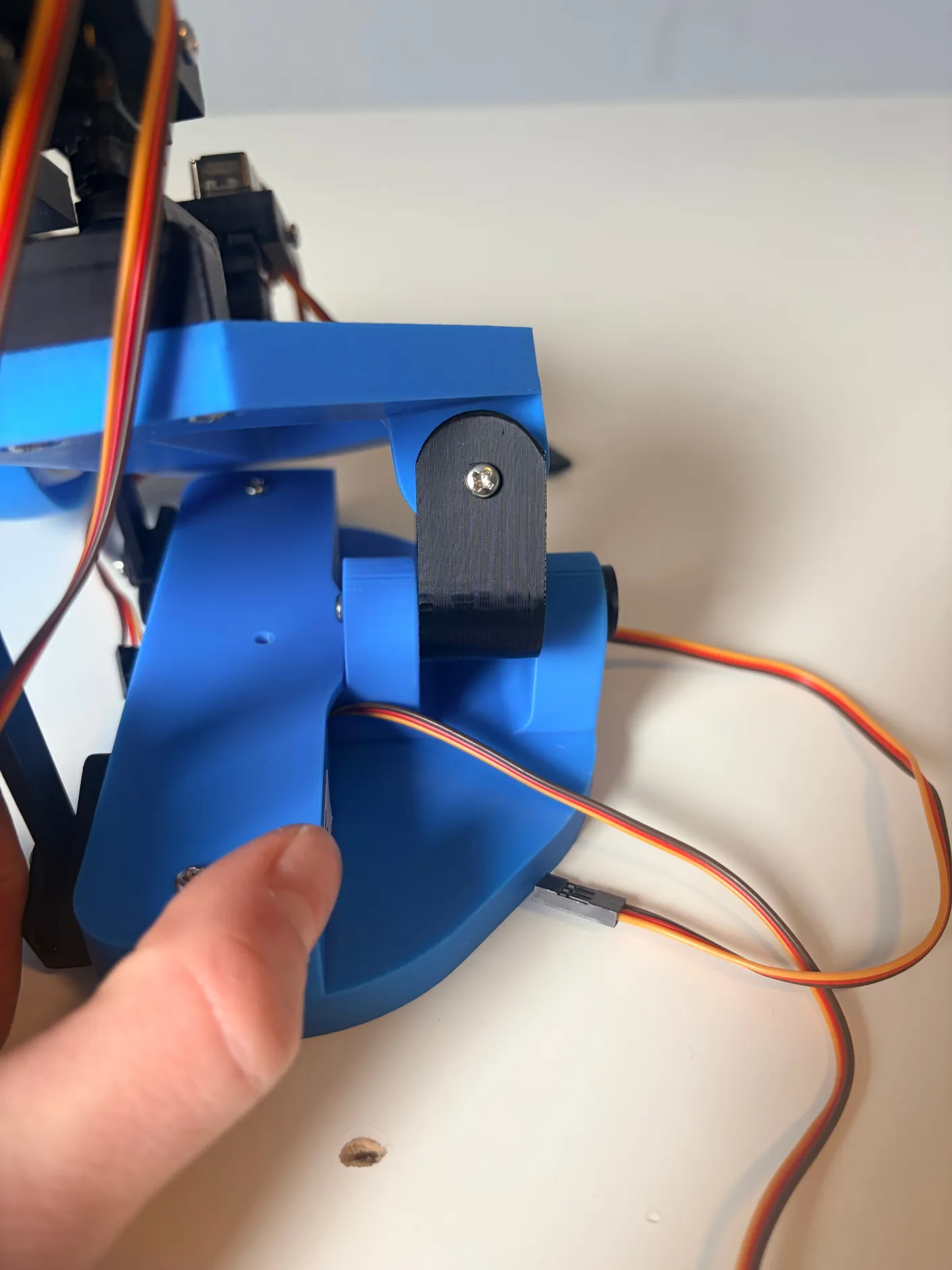
1× 6mm screw
Now connect the up-and-down rods to the eyes themselves.
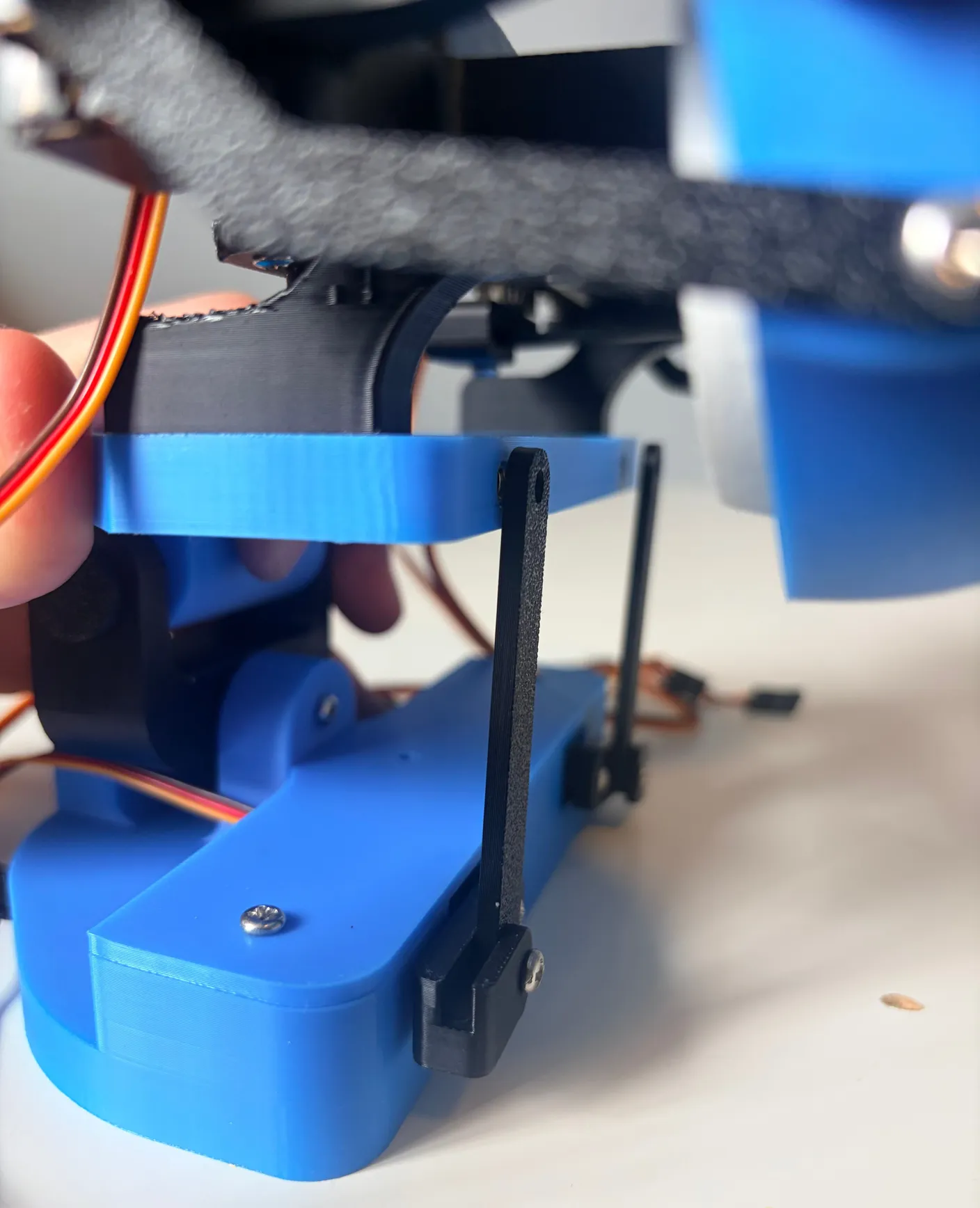
Use two 6mm screws, tightened to a snug fit, as shown. This is another point where the screws should definitely not be tight — if they’re too tight, it won’t allow the robot to move, and could burn out the motors controlling it. So, it’s better to play it safe and keep them fairly loose, and after it operates the first time you can tighten them as you see fit.
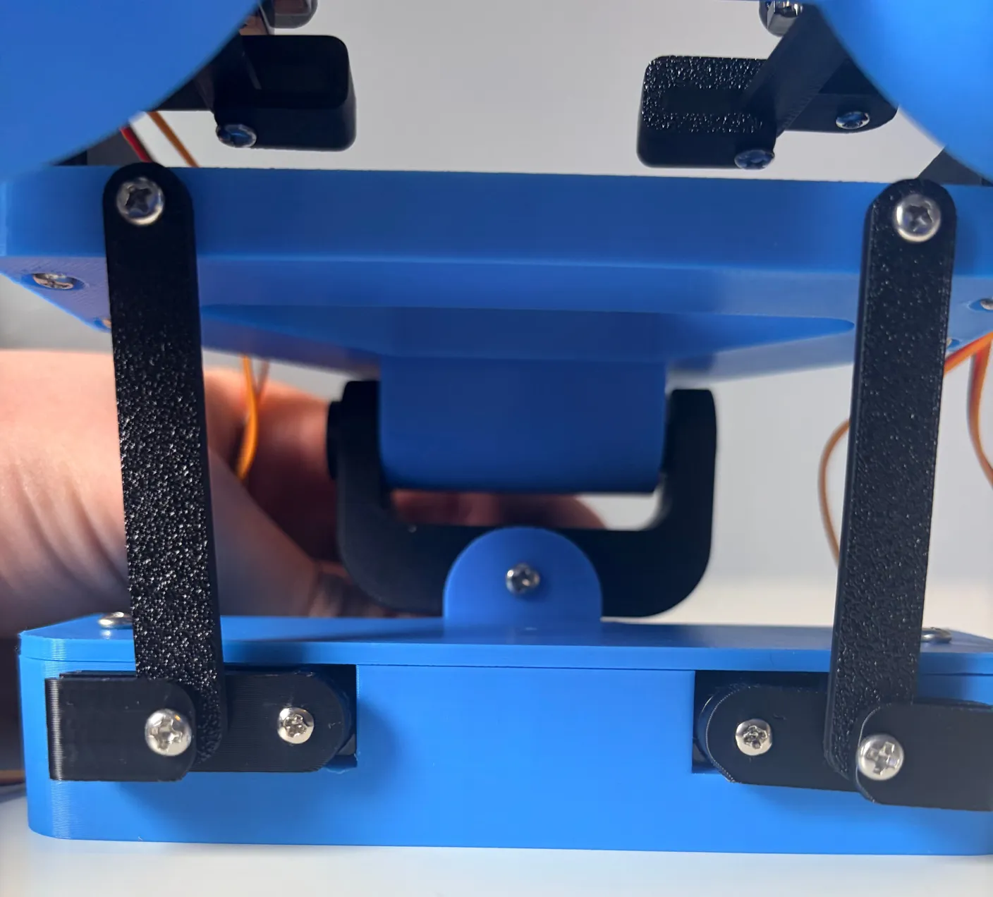
2× 6mm screws
Great work — the eyes and neck are fully assembled. Next, we are going to connect it to the base!
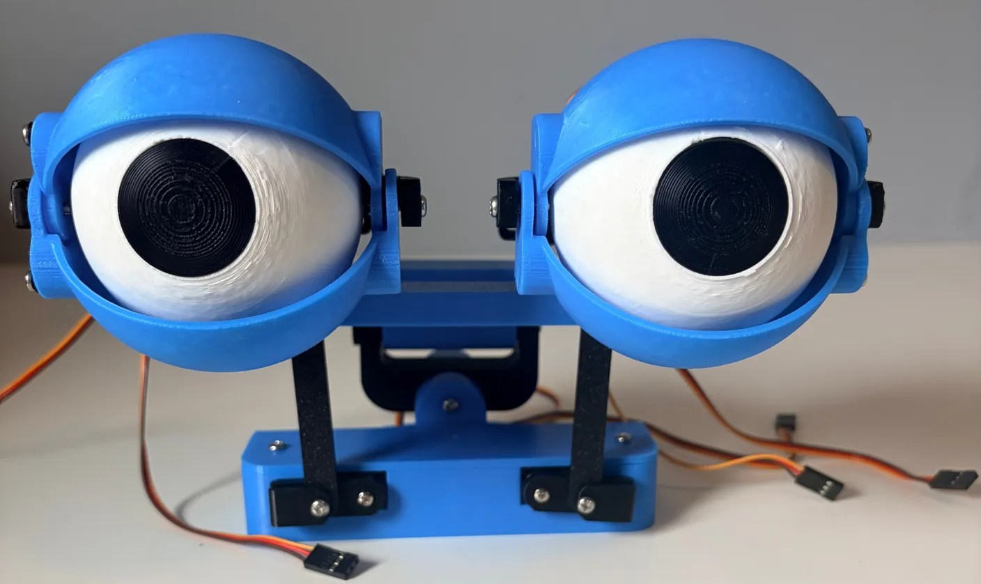
Assemble the Base
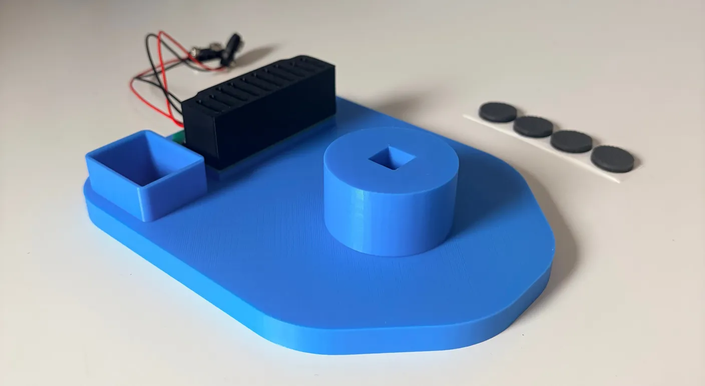
Get the big base and the four adhesive rubber pads.
Note — don’t remove the case
Do not take off the black protective case over the circuit board. It’s there to protect the board, and if you take it off, we won’t be able to offer support. Thank you!
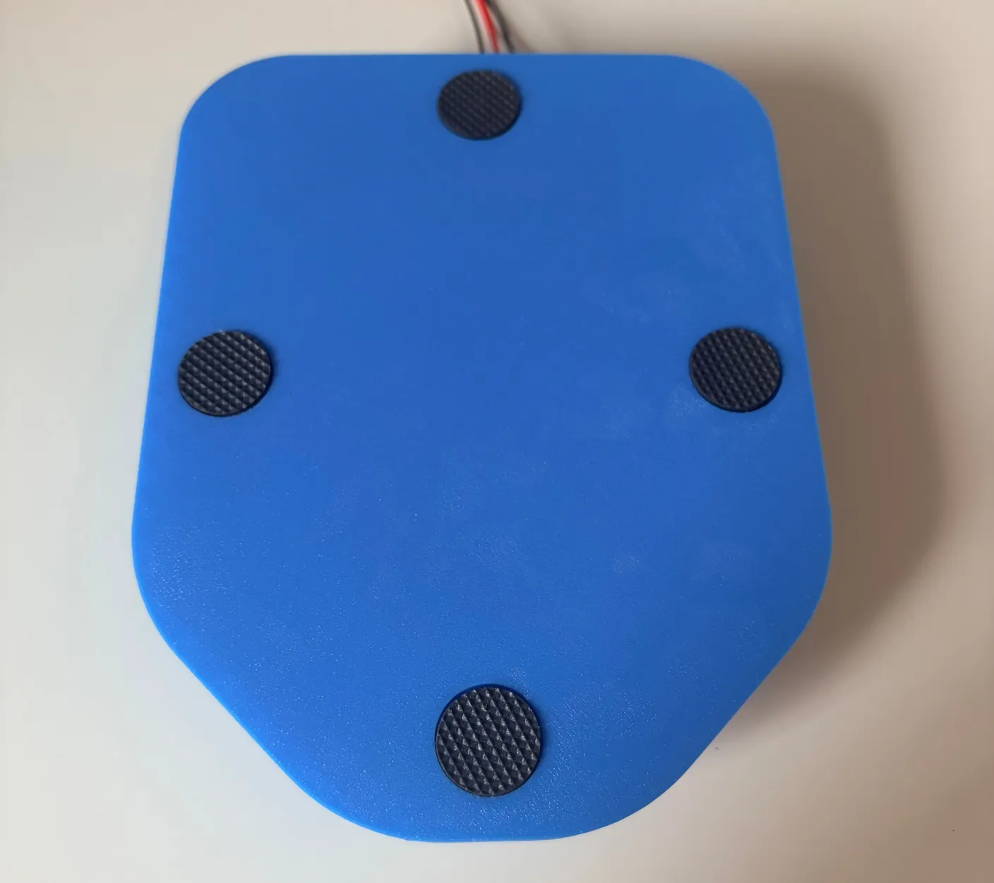
Flip the base upside down. The four indented circles are where the rubber pads go — they keep the robot from sliding around on a surface.
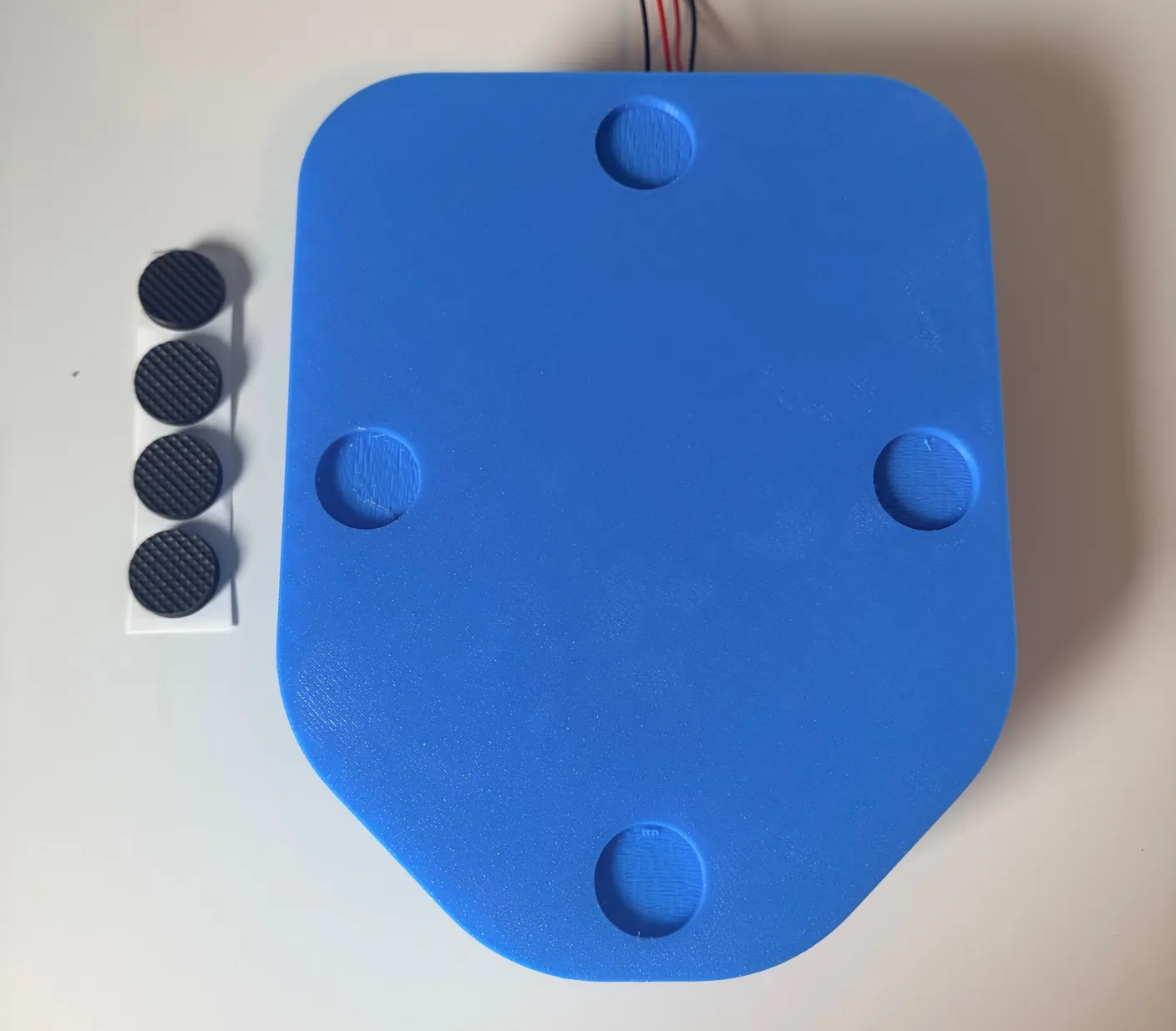
Stick the pads into the circles, as shown.
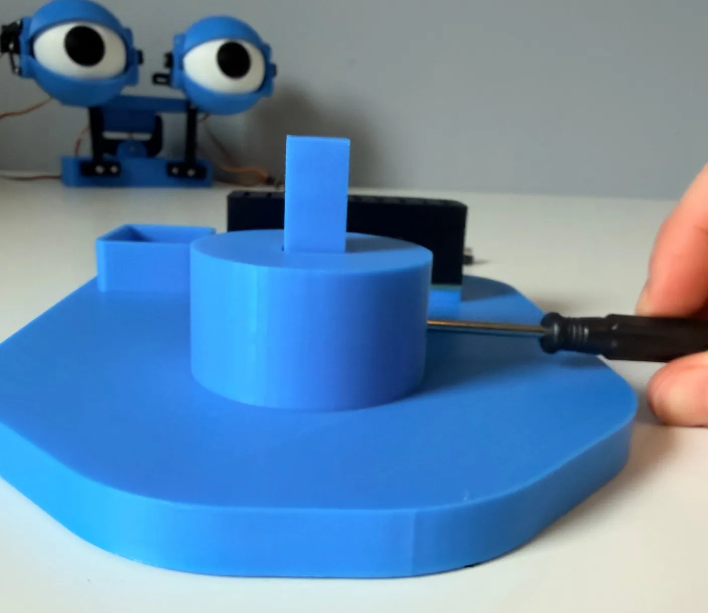
Flip the base back over and find the square pin. Align it as shown below, with its screw hole facing the hole in the base so you can screw it down.
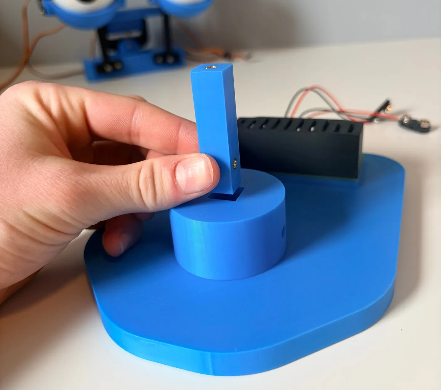
Once it’s in place, secure it with a 6mm screw.
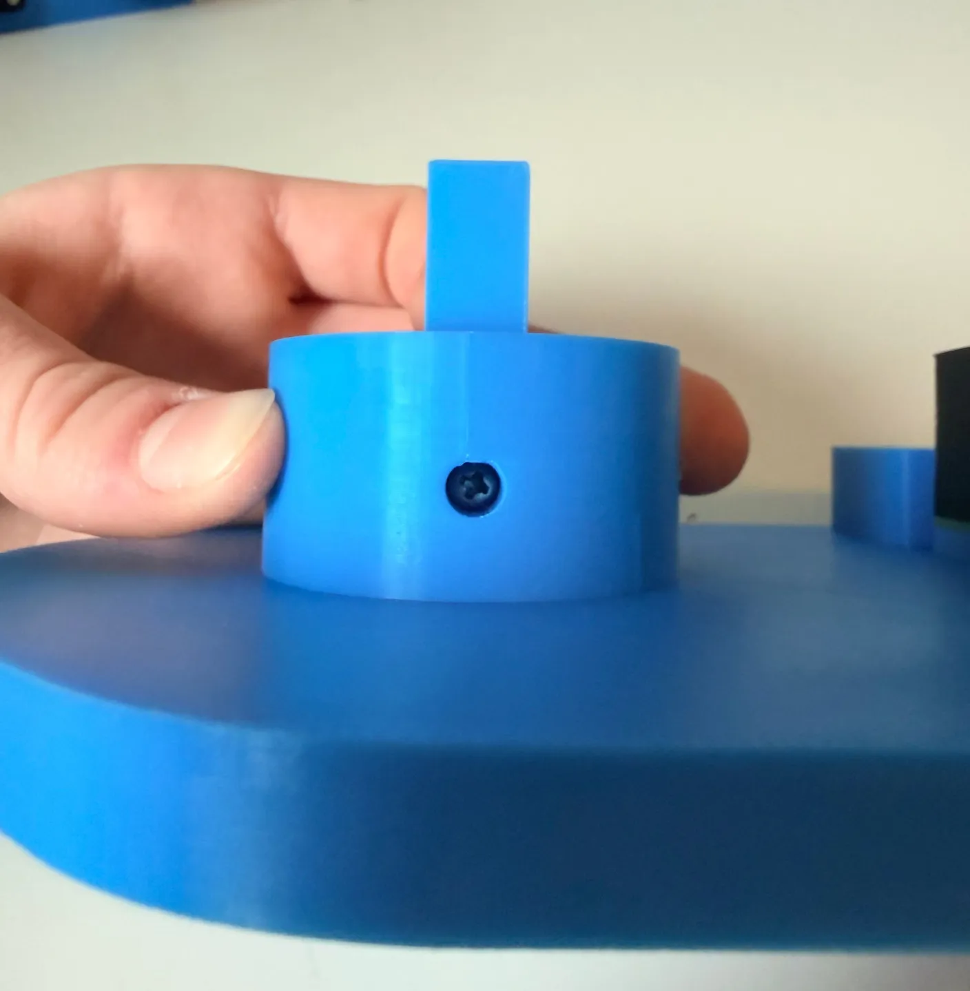
1× 6mm screw
Tighten it all the way. This pin is what the rest of the eye assembly connects to.
Line up the square hole on the eye assembly with the pin you just secured.
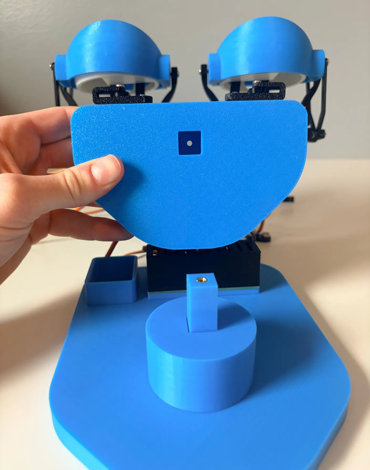
Slide it onto the pin and lock them together with another 6mm screw. Everything is now securely connected.
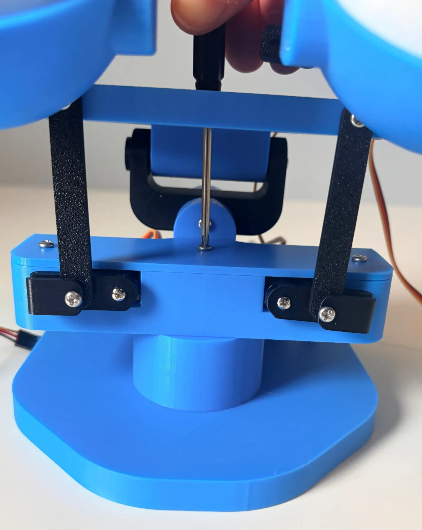
1× 6mm screw
Good work — all the mechanical parts are now assembled and connected. The last step is wiring everything up so the components can talk to each other and bring your robot to life.
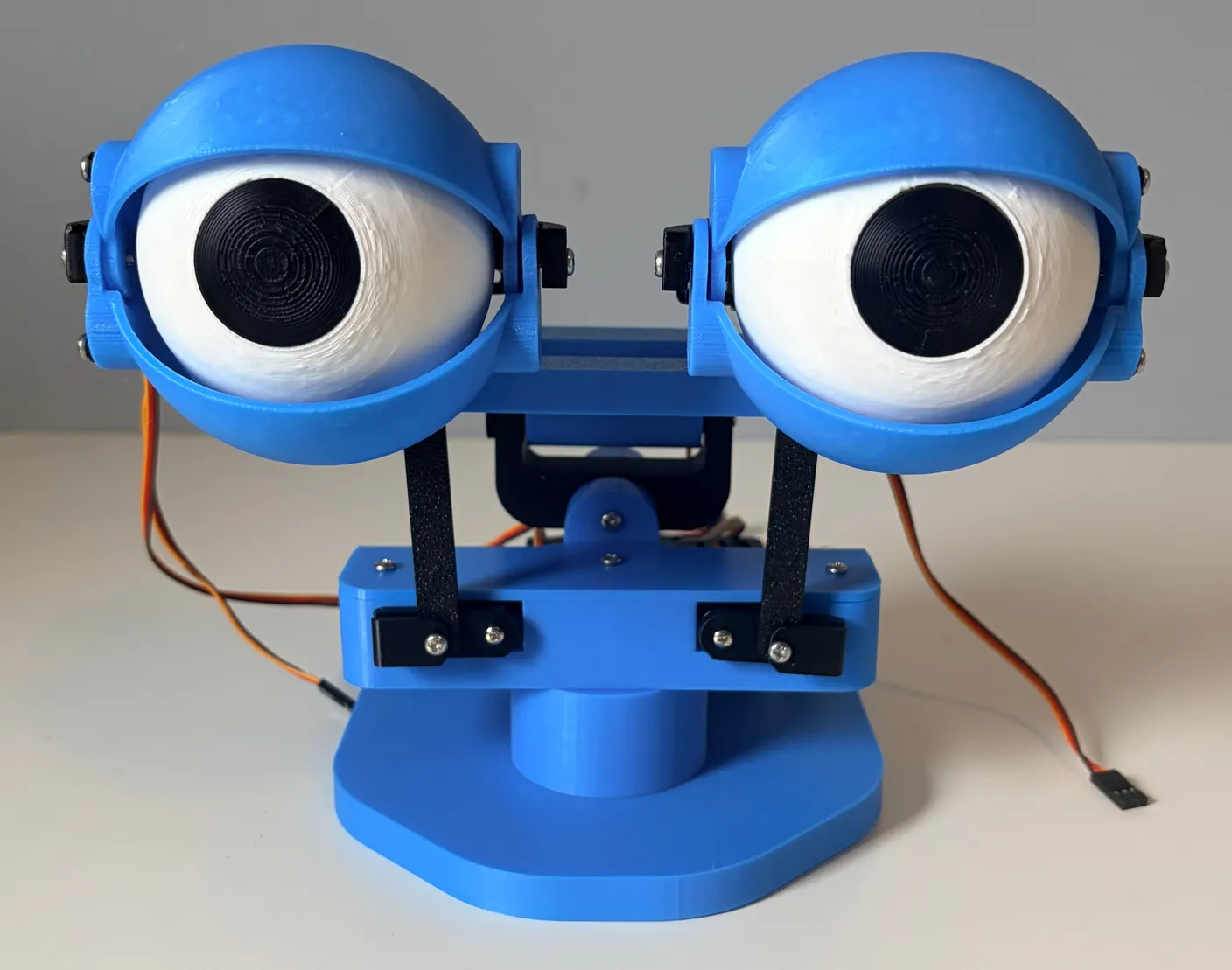
Wire it up
Note — you selected “Both”
You have both the wireless and joystick modules in your kit (at least, that’s what you selected! If this is wrong, feel free to go back to the intro to change your selection). So, we’ll first build it as the joystick kit, and then we’ll show you how to swap it to the wireless version — as well as swapping it back — so you can use whichever version you feel is best!
Time to wire it up. The wiring is designed to be simple, but pay close attention here — misplaced wires can damage your robot. Don’t let that scare you; follow the directions exactly and it’ll work perfectly. Start by facing the back of your robot.
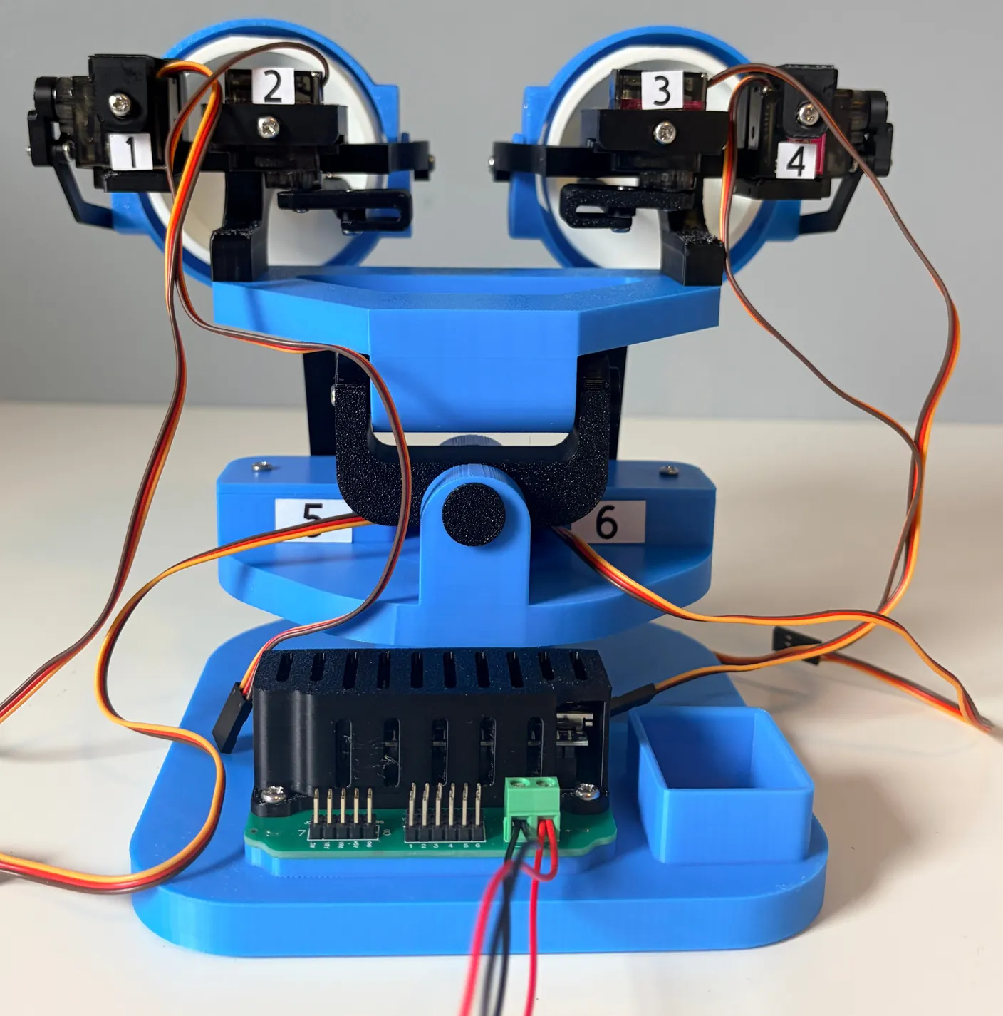
This is the circuit board — where all the electrical signals connect and “talk” to each other. Under the black case is a tiny programmable computer that makes the components work together — an Arduino Nano if you’re controlling it with joysticks, or the wirelessly capable ESP8266 board, when you swap it out for the wireless functionality.
This is the circuit board — where all the electrical signals connect and “talk” to each other. Under the black case is a tiny programmable computer that makes the components work together — it’s called an ESP8266.
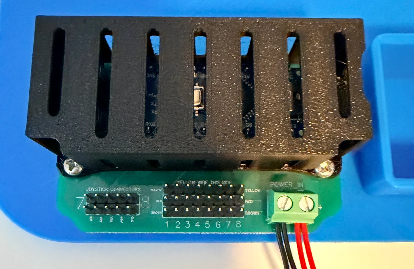
Note — your board may look slightly different
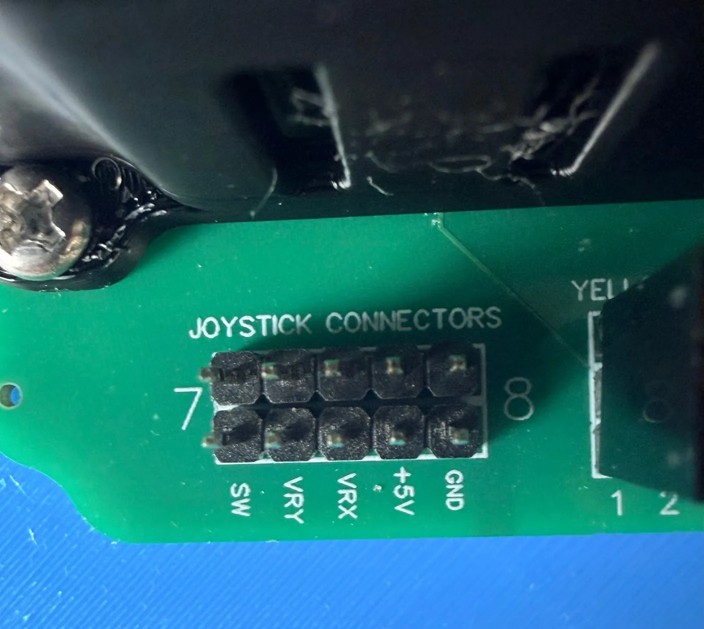
If you’re looking closely, you’ll notice your board has 8 rows of pins and some of the labels on the board are moved around. Don’t worry — it’s the exact same board, just refined and improved over time. Those two extra rows won’t get in your way: this project only uses rows 1–6, and everything else is exactly the same.
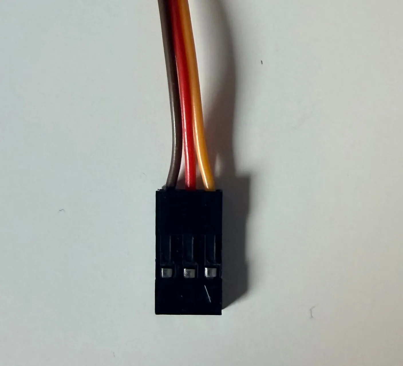
Below is what the servo wire looks like. Notice that it has 3 wires bundled into one connector, and each wire has a different color. This is very important, and we’ll get into the specific wiring details next. It matters because each wire is expecting a specific signal, and if it receives the wrong signal, it could cause damage to the servo motor.
Important!
Wire orientation
Which way the wire faces matters. The servo wire has three colored strands — yellow, red, and brown — and each row of pins on the board is labeled the same way. Line up each strand with its matching label: the yellow strand toward the black box (and toward the “Yellow wire this side” label), and the brown strand facing away from it. Double-check before powering on — a backwards wire can damage your robot.
It’s also extremely important to plug the wire into the right slot. Under each set of three pins is a number, 1 through 6 (this board has a total of 8 rows — we only use 1–6, so don’t be worried when you see that the last 2 rows don’t plug into any servo motors). The wiring is meant to be pretty intuitive. Each servo has a label with a number on it, and you’ll match that number to the number under the row of pins — for example, 1 goes to 1, 2 goes to 2, and so on. It’s very important that you match them correctly, with the correct color orientation, so that your robot works correctly!
The image below shows the first wire being plugged in correctly — the yellow wire is facing the robot, as well as the “Yellow wires this side” label, and the black wire faces away from the robot. Also, this wire comes from servo motor 1, which is why it’s in the #1 spot.
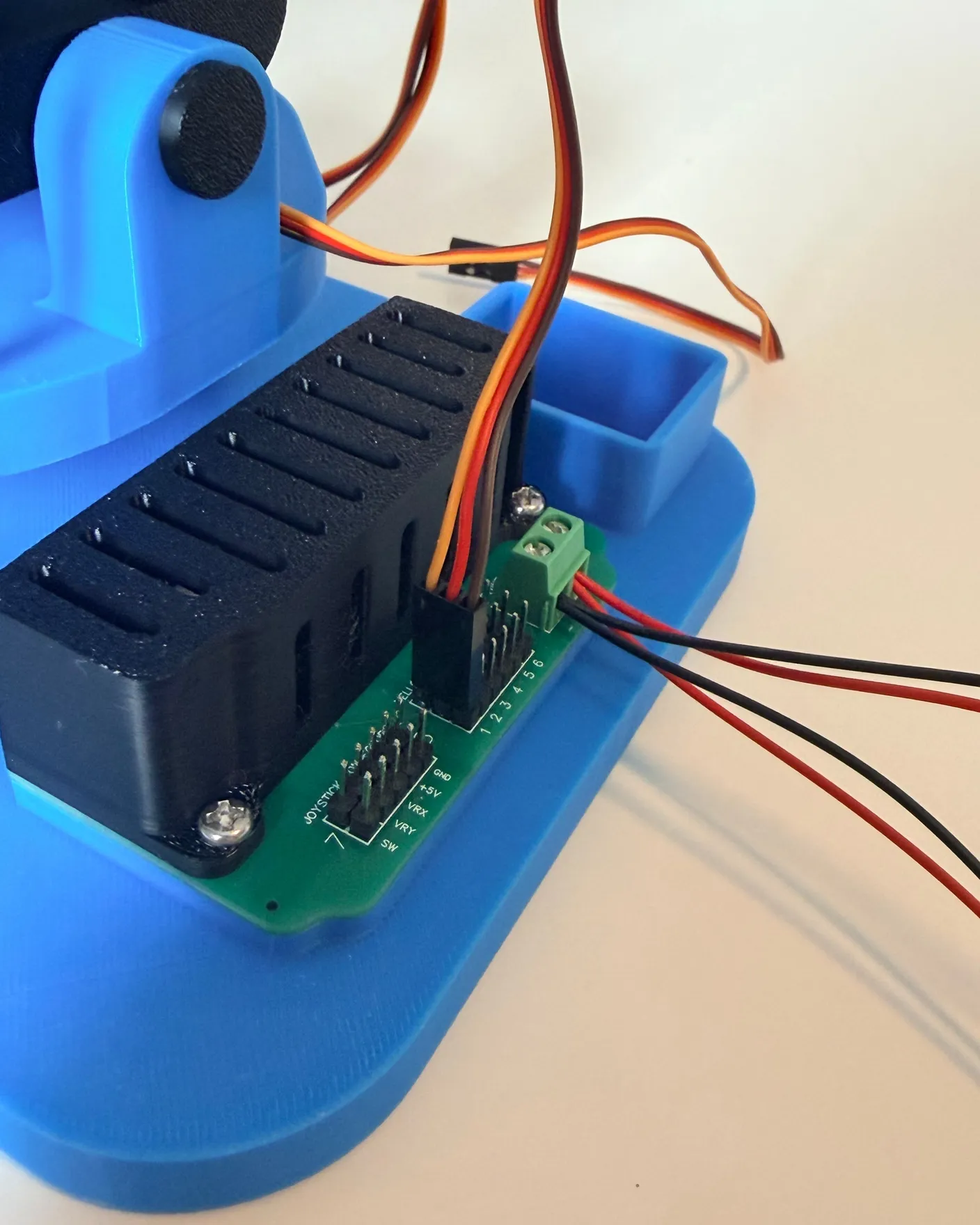
Now it’s your turn to wire every wire up to the board. Remember, all you have to do is match the number on the motor to the number on the board, as well as follow the color orientation rule for the wire: the yellow end plugs into the row labeled yellow, red to red, and brown to brown. Motor 1 plugs into slot 1, motor 2 plugs into slot 2, and so on. Remember, we only use the first 6 rows — the last 2 (labeled 7 and 8) won’t be used for this project.
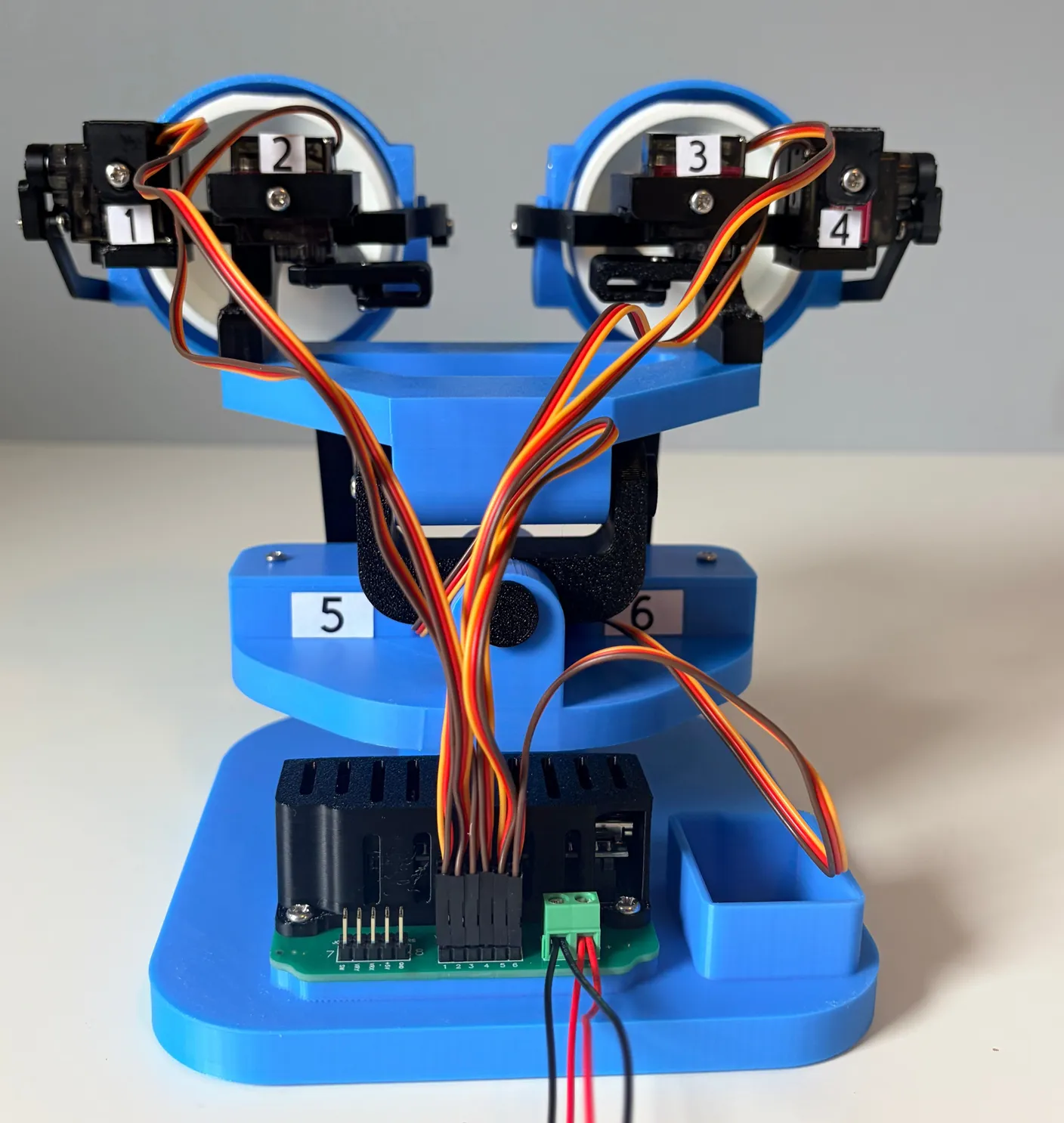
Once they’re all plugged in, it should look like this — every yellow wire facing the robot (the “Yellow wires this side” label) and every brown wire facing away. Double-check that color orientation, then confirm each wire is in its matching pin (1 to 1, 2 to 2, etc.). If everything checks out, nice work — the servos are wired.
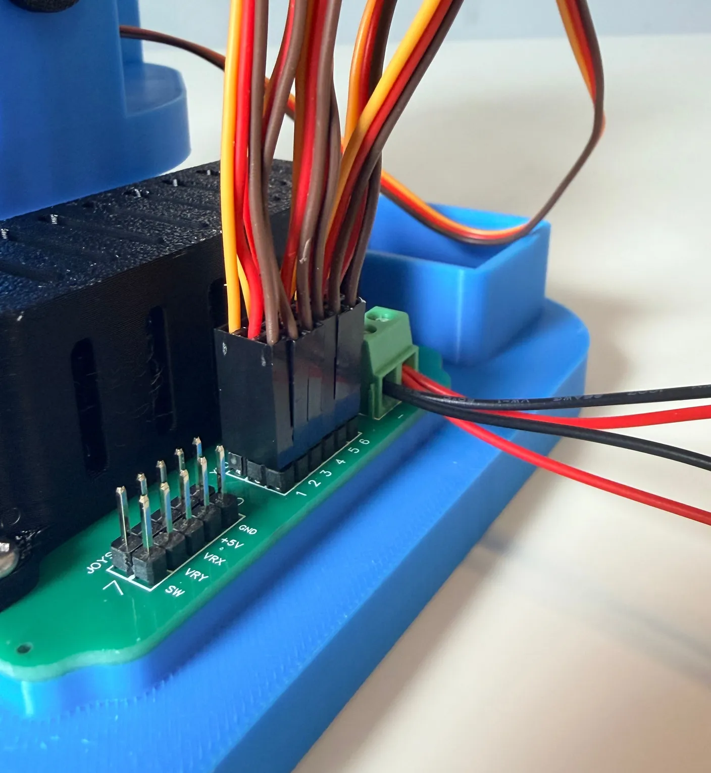
Now we are going to connect the joysticks, which let you control the robot!
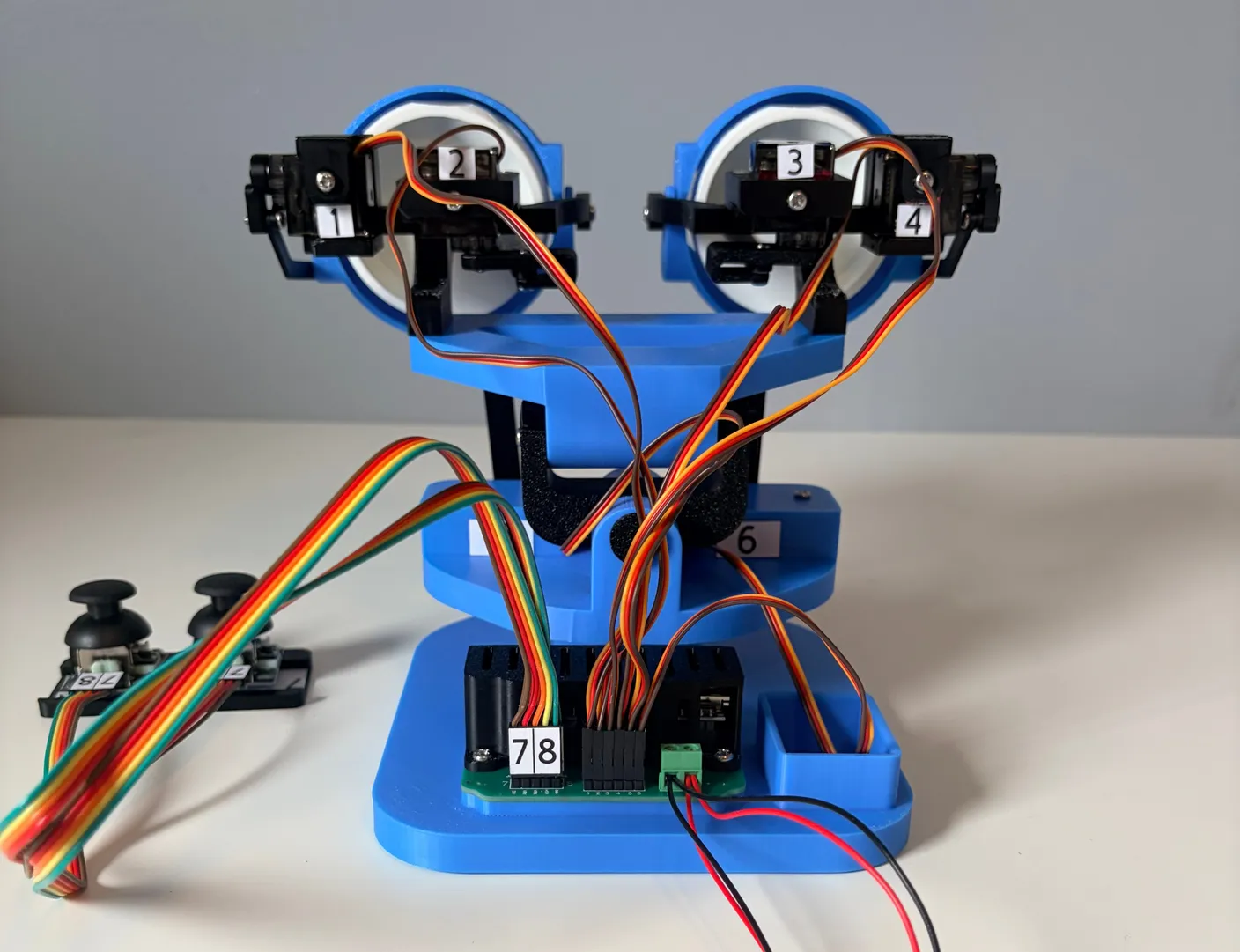
Each side of the joystick connector’s pins is labeled 7 or 8 — that’s how you’ll connect the wires.
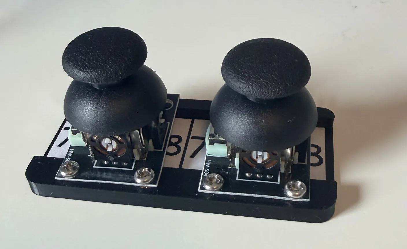
Grab the two long wires that connect the joysticks to the board. Orient the sticker side as shown. Each wire is labeled 7 and 8 to match the joystick board — just line up 7 to 7 and 8 to 8.
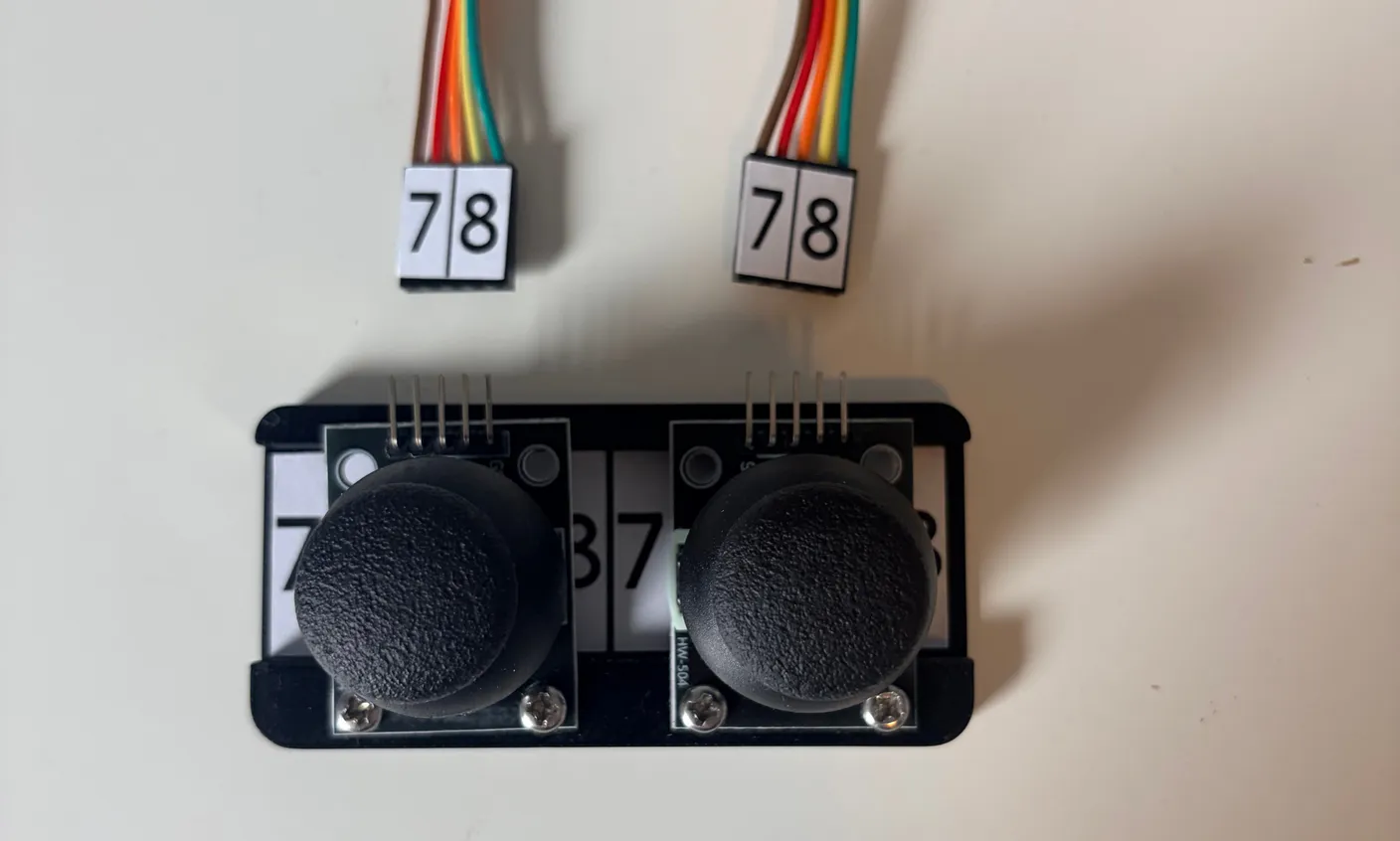
Connect the wires to the joystick by matching the numbers, as shown.
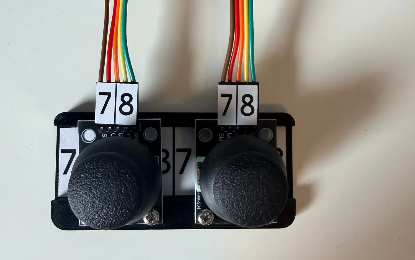
Now plug the other end into the circuit board. It has its own labeled sticker — match 7 to 7 and 8 to 8, with the sticker facing you, exactly like the image below.
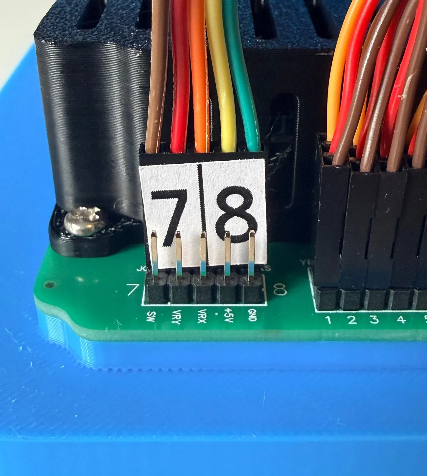
Repeat with the other wire. The order doesn’t matter — as long as 7 matches 7 and 8 matches 8, it works. Once the last wire is in, it should look like the image below. The most important thing is that both stickers (with the 7 and 8 numbers on them) are visible and facing you. If it looks just like the image below, you’re ready to move on!
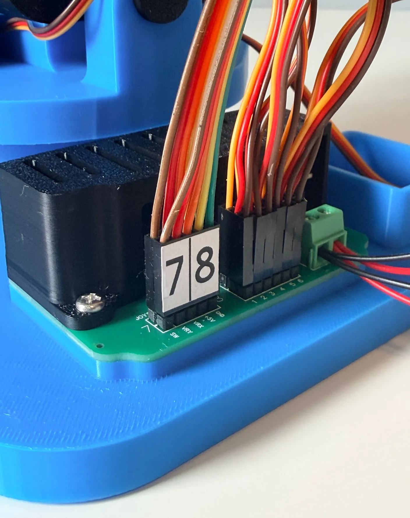
If you are confident that you followed the directions carefully and every wire is plugged in correctly, then congrats! Feel free to keep moving on. If you have any doubt that you may have plugged in a wire wrong in any way, we recommend going back through this section and checking your work — a wrongly placed wire is the number one cause of the robot not working, or potentially damaging itself.
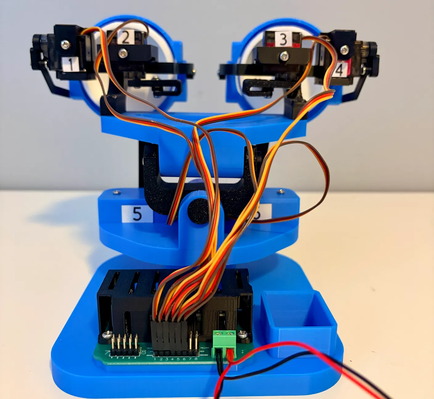
Now that the wiring is done, we can tidy up these loose wires with zip ties. The kit includes 5 zip ties, and you’re free to use them however you see fit for your project. If you want a recommendation, we suggest 3 for the servo wires and 2 to keep the joystick wires tidy. When you go to trim the zip ties, be extra careful not to cut or nick a wire.
Now that the wiring is done, we can tidy up these loose wires with zip ties. The kit includes 5 zip ties, and you’re free to use them however you see fit for your project. If you want a recommendation, we suggest using one zip tie to bundle motors 1 and 2, another for motors 3 and 4, and 1 or 2 zip ties to bundle the 9-volt battery connector together with the wires at the base. When you go to trim the zip ties, be extra careful not to cut or nick a wire.
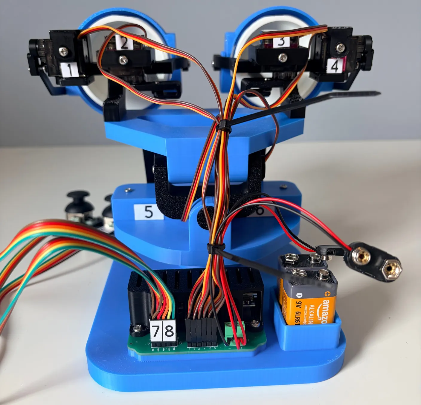
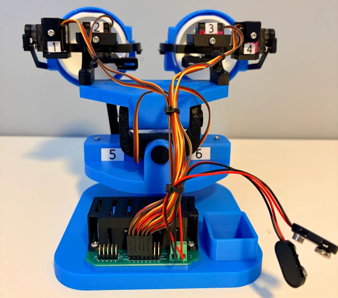
That’s the build finished — every part assembled and every wire in place. Stick around for the last section to learn how to control it.
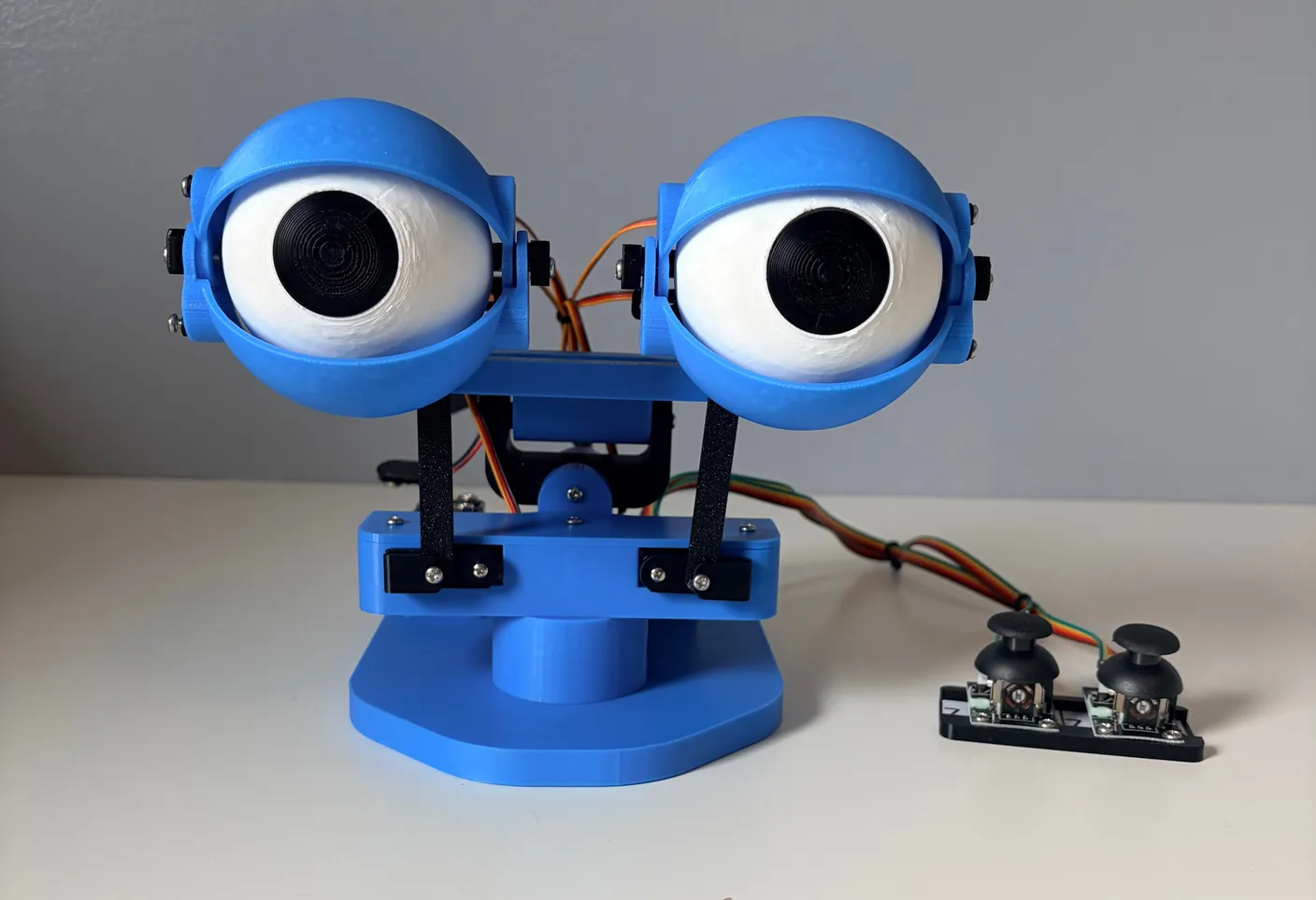
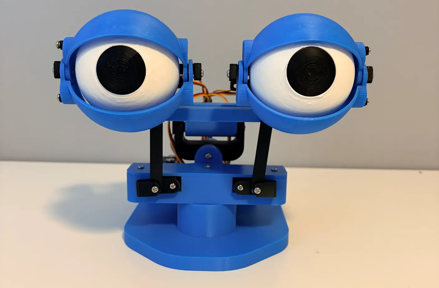
Guess what? You just finished building a really cool robot! Whether you’re a beginner or an expert, completing a project and seeing it actually work is an incredibly rewarding experience. This feeling—turning an idea into something real—is what robotics is all about, and it’s a feeling many people end up chasing once they discover a passion for it. Enjoy your robot, and have fun exploring what it can do!
How to Operate
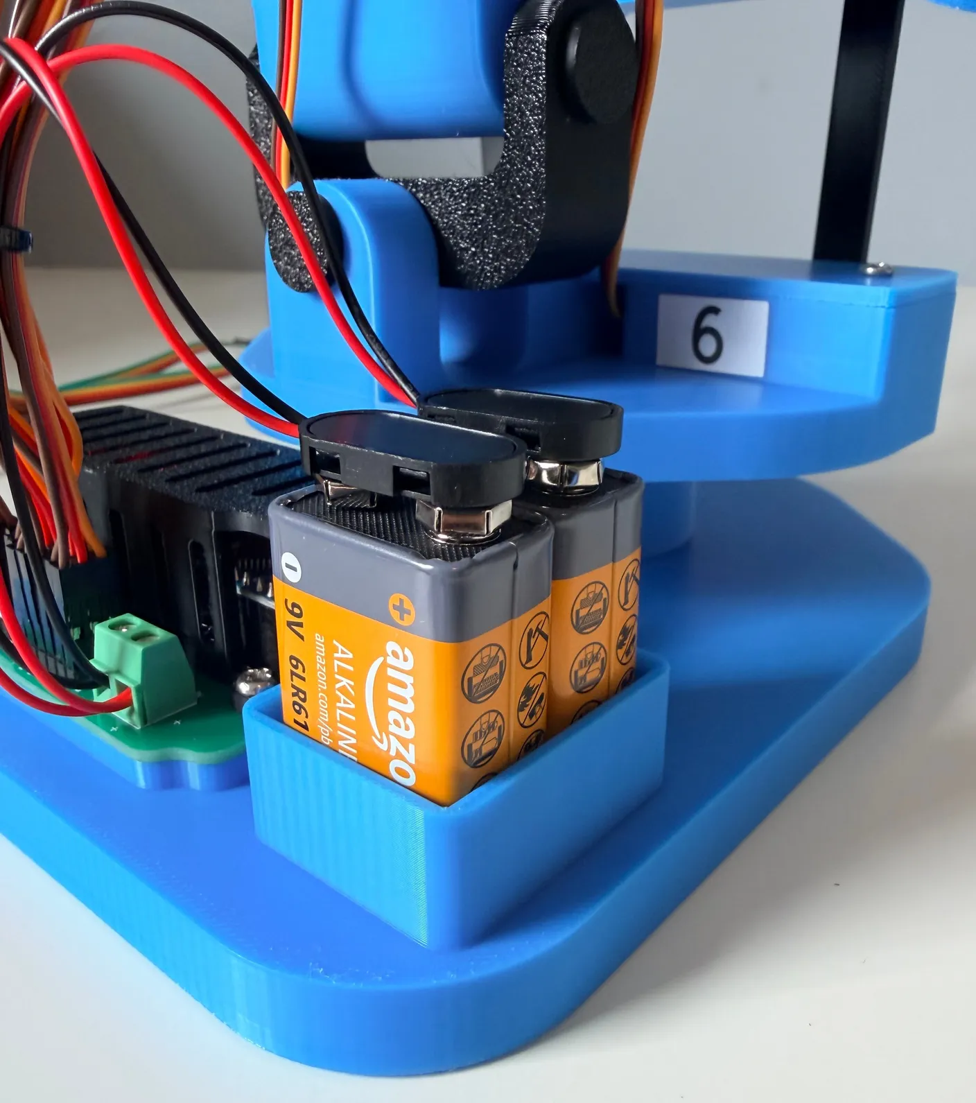
Now that your robot is fully built, it’s time to bring it to life! Below you’ll find instructions on how to power it on, operate it, and keep it running smoothly, along with some helpful tips.
Joystick-Controlled Kit
Powering On the Robot
Start by plugging BOTH 9-volt battery connectors into the batteries. Using both batteries is important—if only one is connected, the robot will be underpowered, which can cause poor performance or unexpected shutdowns. Once both batteries are connected, the robot will be ready to use. Always unplug both batteries when you’re done using it, or they’ll drain and die.
Operating the Robot
You will use the two joysticks to control the robot. Joystick 1 controls the neck movement, allowing it to move up, down, left, and right. Joystick 2 controls the eyes, including blinking and eye movement. Take your time and experiment with the controls to get a feel for how the robot responds.
Operation Notes
The robot is designed to be operated in a calm, controlled manner. Rapid or aggressive inputs can cause it to draw too much power too quickly, which may result in a temporary shutdown. If this happens, simply wait a few seconds and the robot will power back on. This behavior can also occur when the batteries are starting to run low.
Screws & Maintenance
With anything that moves, screws can occasionally loosen over time. If you notice any parts feeling loose, just tighten the screws back down snugly. The most common screws to loosen are the two 16mm screws that hold the eyes in place, due to frequent movement.
Battery Information
The two included 9-volt batteries will last a while, but they will eventually need to be replaced. You’ll know the batteries are running low if the robot starts moving more slowly or randomly shuts off. When this happens, replace them with two standard 9-volt batteries. We recommend the Amazon Basics 9-volt batteries that came with the kit.
Later — once you’ve swapped the control board for the wireless control board. See the “Swap from Joystick to Wireless” section below to do this.
Wirelessly-Controlled Kit
Powering On the Robot
Start by plugging BOTH 9-volt battery connectors into the batteries. Using both batteries is important—if only one is connected, the robot will be underpowered, which can cause poor performance or unexpected shutdowns. Once both batteries are connected, the robot’s WiFi will switch on and it will be ready to use.
To control your robot, you’ll need a device with WiFi capabilities — most likely whatever you’re reading this tutorial on right now, like your phone, tablet, or computer.
Open your device’s Settings app. This tutorial uses an iPhone for the screenshots, but Android and Samsung devices work exactly the same way — just look for the Wi-Fi setting on your specific device. From Settings, navigate to Wi-Fi.
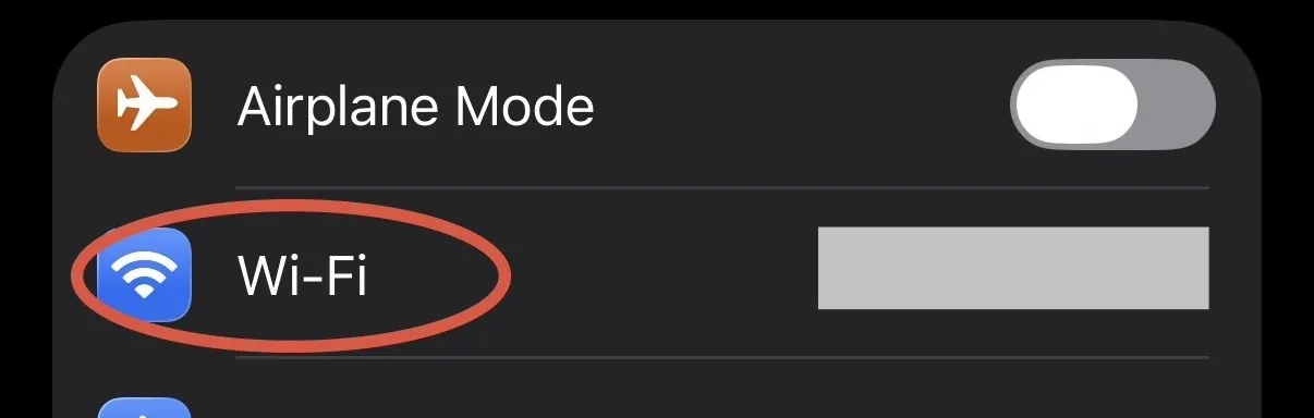
You should see a network called “RobotEyes” in the list (only if your robot is plugged in). If this is your first time connecting, it will likely be listed under “Other Networks.” Tap on it and wait a moment for a control screen to pop up.
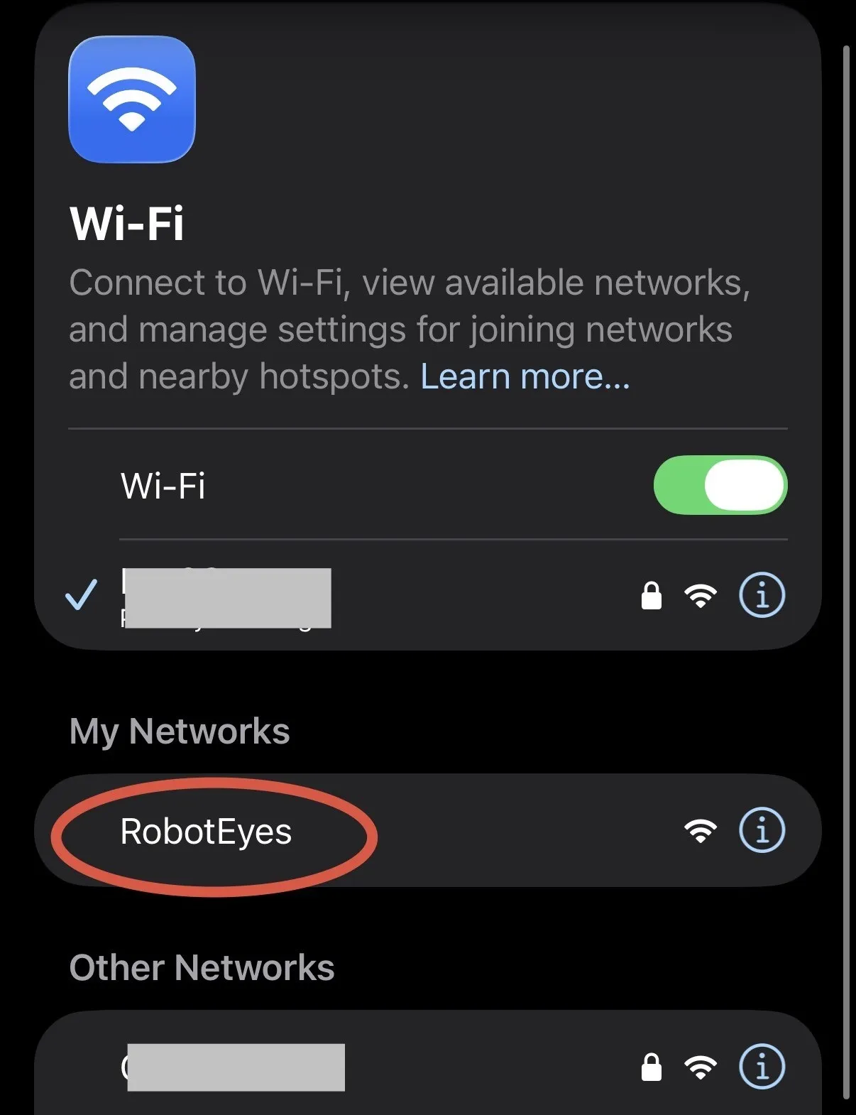
If you’ve connected to “RobotEyes” before, that pop-up screen won’t appear automatically. In that case, just open a web browser and type exactly: “192.168.4.1” into the address bar.
Note — connection problems
If you’re having trouble connecting to the robot, there are a few common causes. First, make sure both batteries are plugged in and the light on the circuit board is on. If the “RobotEyes” network doesn’t show up, try unplugging the batteries and plugging them back in. If you still don’t see it, turn your Wi-Fi off and back on, then wait a minute — sometimes it takes a while to be discovered. And if you can see the network but tapping it says it can’t connect, try a different device; this is usually caused by a setting on your device that’s blocking the network.
Once you see the control page below, you did it — you’re connected! The controls are pretty intuitive, but if you ever need a refresher, tap the “Tutorial” button at the top of the page for a full explanation of every control.
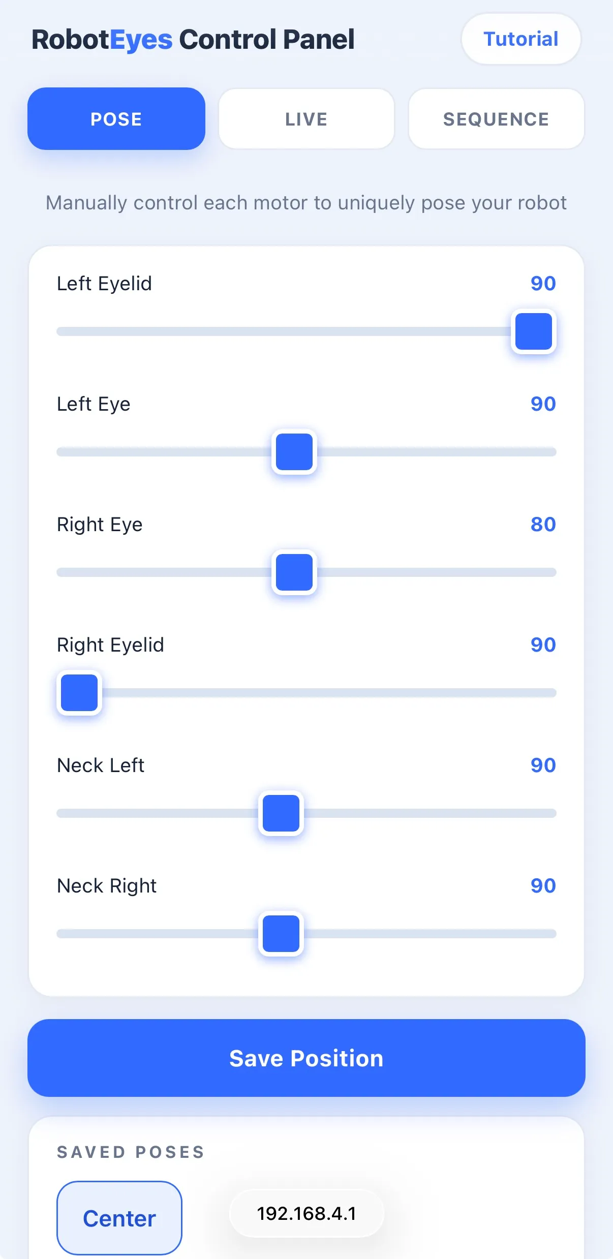
Operating the Robot
The control page has three tabs. The Pose Page gives you a slider for each motor, so you can pose the robot exactly how you want and save named positions to recall later with one tap (a built-in “Center” pose resets everything to neutral). The Live Page gives you a slider to move the eyes side to side, an on-screen joystick to aim the neck, and a Blink button, all in real time. The Sequence Page lets you program the robot to run through a set of movements you define, one after another. Tap “Tutorial” at the top of the page any time for a refresher on the controls.
Operation Notes
The robot is designed to be operated in a calm, controlled manner. Rapid or aggressive inputs can cause it to draw too much power too quickly, which may result in a temporary shutdown. If this happens, simply wait a few seconds and the robot will power back on. This behavior can also occur when the batteries are starting to run low. When you’re finished, disconnect from the “RobotEyes” network to get your phone’s normal internet access back, and unplug the batteries to save power.
Screws & Maintenance
With anything that moves, screws can occasionally loosen over time. If you notice any parts feeling loose, just tighten the screws back down snugly. The most common screws to loosen are the two 16mm screws that hold the eyes in place, due to frequent movement.
Battery Information
The two included 9-volt batteries will last a while, but they will eventually need to be replaced. You’ll know the batteries are running low if the robot starts moving more slowly, disconnects from WiFi, or randomly shuts off. When this happens, replace them with two standard 9-volt batteries. We recommend the Amazon Basics 9-volt batteries that came with the kit.
Frequently Asked Questions
Can I use it from another device?
Yes, but it must be connected to the “RobotEyes” WiFi network before you can control it. Only one device can be connected at a time.
Can I use it in another browser?
Yes — just make sure you’re connected to the “RobotEyes” WiFi network, then open your preferred browser and type 192.168.4.1 into the address bar.
Can I access the internet while connected?
Simple answer: no. However, if you’re on a mobile device with cellular data, you can keep using cellular data as normal — the robot doesn’t provide internet access, and it doesn’t even connect to your home network.
Can I reprogram it or modify the kit?
Our policy is that we want you to get the original kit fully working first. After that, we can’t tell you what to do — you’re curious and want to play around, and that’s exactly why you’re here! But once a kit has been modified in any way, we’re no longer able to provide support, help fix it, or send replacement parts. Thank you!
Swap from Joystick to Wireless
Your kit came with both control options, so once you’ve built the robot with joysticks and had a play with it, you can switch it over to wireless. It only takes a few minutes and nothing you’ve built comes apart — you’re swapping the small blue Arduino Nano for the ESP8266 wireless board that came in the grey bag, and everything else stays exactly as it is.
Before you start, unplug both batteries so the robot has no power.
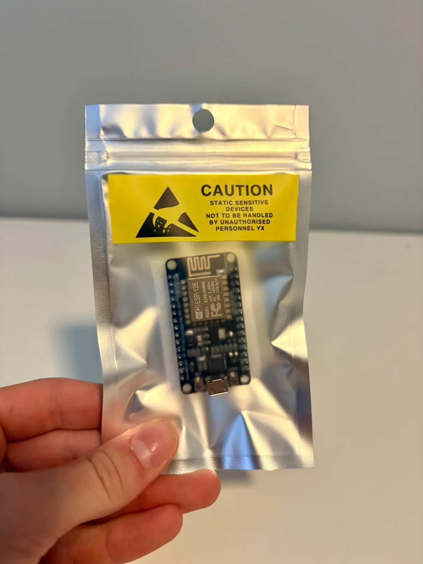
Find the grey bag with a circuit board in it. It’s called an antistatic bag, and it protects the sensitive electronics inside.
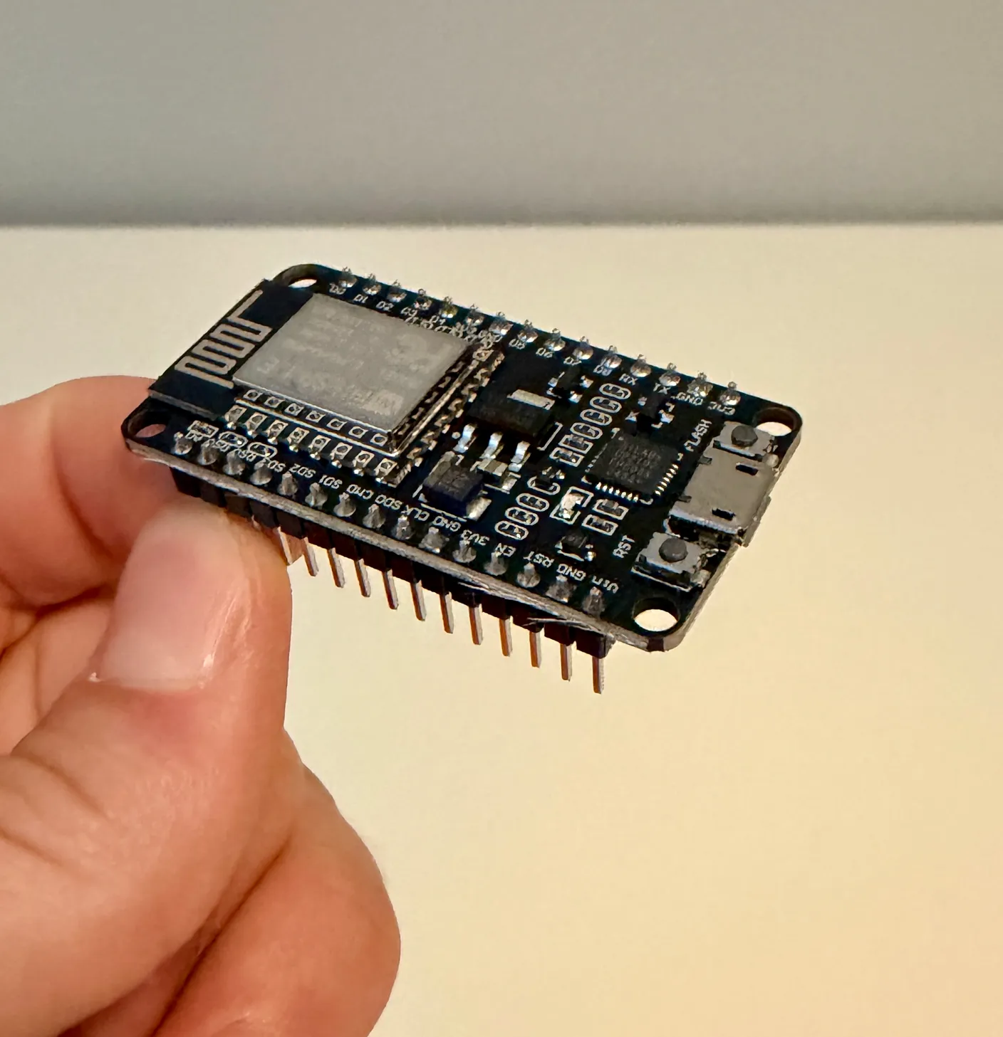
Take out the circuit board and remove the foam from underneath it. This board is called an ESP8266, and it has wireless capabilities.
Now unplug all the wires so you can get to the circuit board.
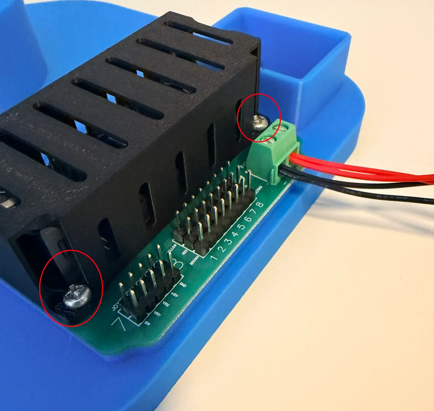
Unscrew the two screws circled in red above. These screws hold the circuit board in place, along with the protective cover. Be gentle and careful not to damage the board or bend any pins.
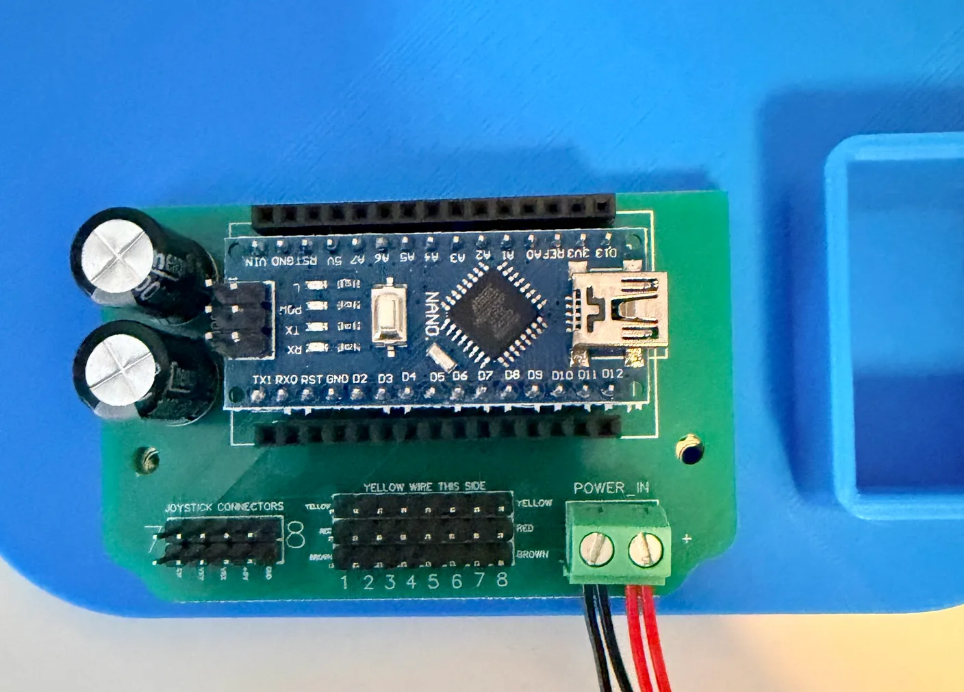
Once the protective cover is off, this is what you’ll see. The blue board is called an Arduino Nano — it’s what’s controlling your robot right now. It doesn’t have wireless capabilities, though, which is why we’re going to swap it out.
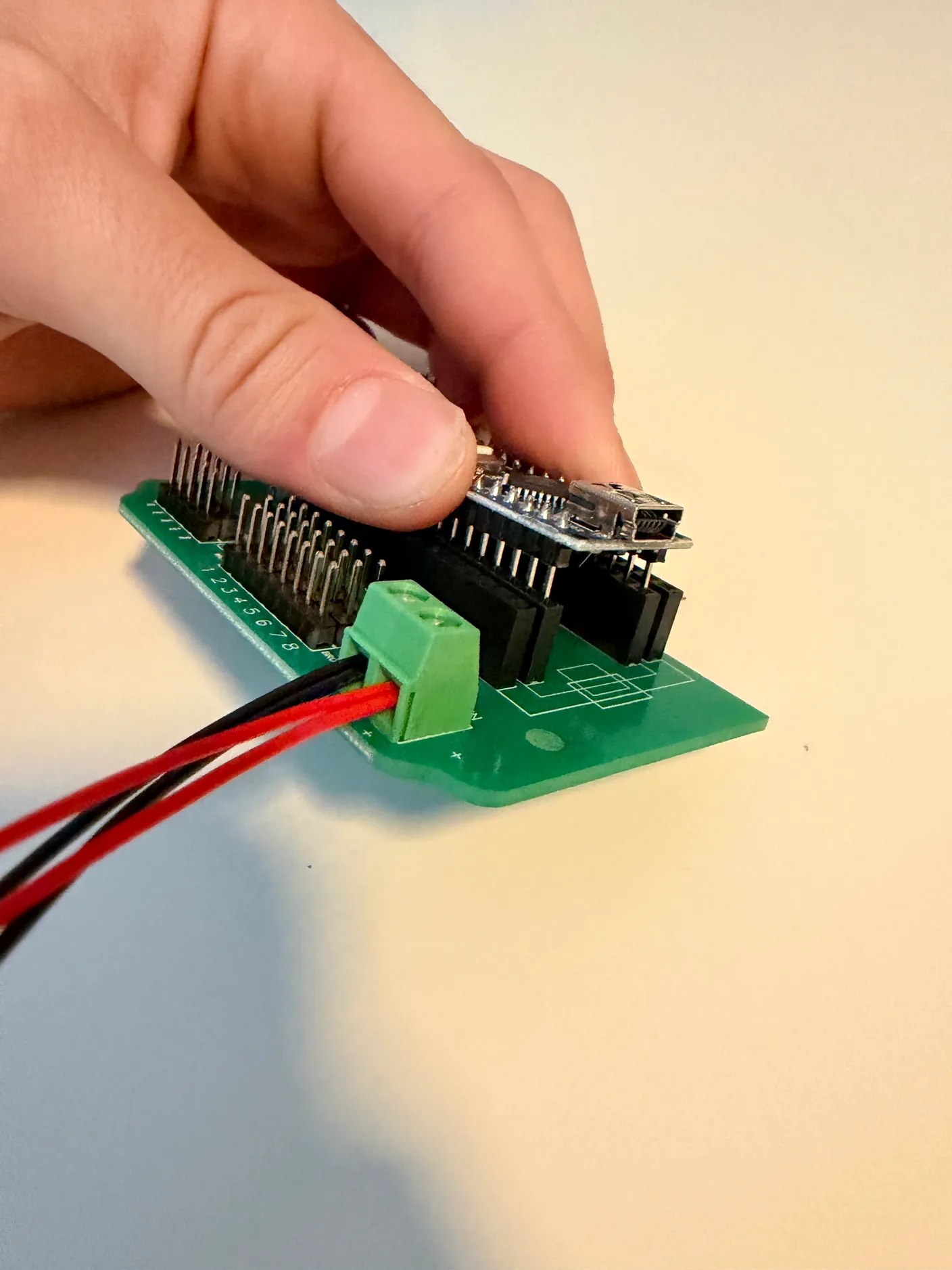
Now gently remove the Arduino from the circuit board, being very careful not to bend any of its pins. We recommend loosening it and pulling it up slightly on one end, then the other, until it slides fully out. Feel free to take the board off the robot to give yourself more space and make it easier.
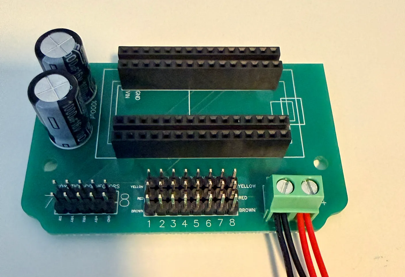
Once it’s out, you’re left with the bare circuit board.
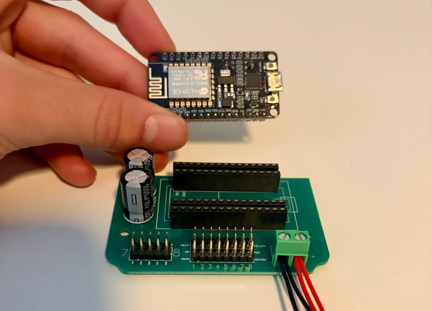
Now get the ESP8266 you took out of the bag earlier. This board plugs in similarly to the Arduino Nano, but it has a different set of pins — this one plugs into the outer set of pins.
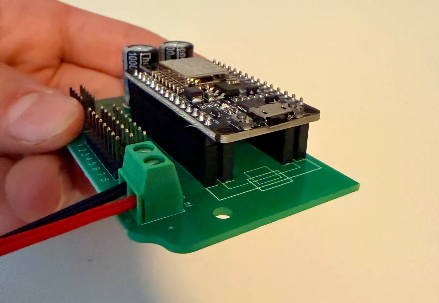
Once connected, it will look like the image above.
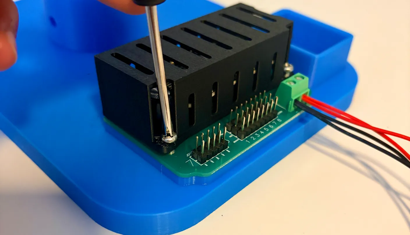
Finally, screw the board back into place. Then you can plug the servos back into their original positions — remember to match servo 1 to row 1, 2 to 2, and so on. You won’t have to plug the joysticks back in if you’ve swapped to the wireless version, since they aren’t used. To learn how to operate it, scroll back up to the How to Operate section and this time follow the wireless instructions.
This process is the same both ways. If you want to use joysticks, put the Arduino Nano back in; if you want to control it wirelessly, plug the ESP8266 back in. Remember that you can’t control it with joysticks and wirelessly at the same time.
Troubleshooting
Running into an issue? We’ve put together a troubleshooting guide covering the most common problems and how to easily fix them.
View the troubleshooting guideBonus Content
The official tutorial is officially over… so why are you still here? It’s because you’re one of the curious ones. You didn’t just want to build the robot—you want to understand how it works. And honestly, that curiosity is one of the most important skills in engineering and robotics.
Below is the code for the joystick-controlled version of the kit — the exact sketch that comes pre-programmed onto its board. If you’re a beginner and want to learn more about coding and engineering, one great way to do that is to copy this code and paste it into an AI, then have it explain what each part does. It might feel like cheating at first, but in reality, this is how many real programmers learn and improve.
So go ahead—dig in, explore the code, and see what makes your robot come to life!
Joystick-Controlled Kit
/*
 * RobotEyesJoystick — two-joystick control for a six-servo animatronic eye
 * mechanism: two eyelids, two eyes, and two neck servos, driven by an Arduino.
 *
 * Both joysticks are read continuously and mapped straight onto the servos, so
 * the robot mirrors your hands in real time. There is nothing to connect to and
 * nothing to configure — power the board and it runs.
 *
 * WHAT EACH STICK DOES
 *   Joystick 1, up/down    Moves both eyes together, side to side.
 *   Joystick 1, left/right Opens and closes the eyelids as a mirrored pair.
 *   Joystick 2             Aims the neck: up/down tilts, left/right turns.
 *
 * HOW IT WORKS
 *   A joystick is just two potentiometers, so analogRead gives a number from
 *   0 to 1023 with about 512 at rest. Each axis is scaled into an angle, held
 *   inside the arc its linkage can physically reach, and then — for the eyes
 *   and neck — eased toward rather than snapped to, which is what keeps the
 *   movement smooth instead of twitchy. The loop repeats about 100 times a
 *   second, so the easing plays out over a fraction of a second.
 *
 * REQUIREMENTS
 *   The Servo library, which ships with the Arduino IDE. Nothing else to install.
 */

#include <Servo.h>

// S1/S4 are the eyelids, S2/S3 the eyes, S5/S6 the neck.
Servo s1, s2, s3, s4, s5, s6;

// --- JOYSTICK PINS ---
const int joy1X = A0;
const int joy1Y = A1;
const int joy2X = A3;
const int joy2Y = A4;

// --- TUNING PARAMETERS ---
// The smooth factors set how much of the remaining distance a servo closes each
// time through the loop: higher is faster and snappier, lower is slower and
// heavier. The neck carries the most weight, so it gets the gentlest value.
// The deadzone ignores small readings around centre, since a joystick at rest
// never sits at exactly 512 and would otherwise drift.
float smoothFactor = 0.1;
float NeckSmoothFactor = 0.07;
int deadzone = 15;

// Eased positions the servos are actually written to, updated a step at a time.
float cur3, cur2, cur5, cur6;

void setup() {
  Serial.begin(9600);

  // Attach each servo to its pin.
  s1.attach(2); s2.attach(3); s3.attach(4);
  s4.attach(5); s5.attach(6); s6.attach(7);

  // Start every smoothed servo from centre so nothing lurches on the first pass.
  cur5 = cur6 = 90;
  cur3 = cur2 = 90;
}

void loop() {
  // ==========================================
  // --- JOYSTICK 1 Y-AXIS (Servos 3 & 2) ---
  // ==========================================
  // Both eyes track this one axis, so they always look the same direction.
  int rawY1 = analogRead(joy1Y);

  if (abs(rawY1 - 512) < deadzone) rawY1 = 512;

  // Scale the reading to an angle, then keep it inside the eyes' travel.
  int targetY1 = map(rawY1, 0, 1023, 0, 180);
  targetY1 = constrain(targetY1, 45, 140);

  // --- SMOOTHING ---
  // Close part of the gap to the target rather than jumping to it outright.
  cur3 += (targetY1 - cur3) * smoothFactor;
  cur2 += (targetY1 - cur2) * smoothFactor;

  s3.write((int)cur3);
  s2.write((int)cur2);


  // ==========================================
  // --- JOYSTICK 1 X-AXIS (Servos 4 & 1) ---
  // ==========================================
  // Only half of this axis is used: anything from centre downward clamps to 90,
  // which holds the eyelids open, so it takes a deliberate push to close them.
  int rawX1 = analogRead(joy1X);

  int activeAngleX = constrain(map(rawX1, 0, 1023, 0, 180), 90, 180);

  // The two lids are mirrored — one closes by counting up, the other by counting
  // down — and both are written straight through, so a blink lands instantly.
  s4.write(map(activeAngleX, 90, 180, 90, 150));

  s1.write(map(activeAngleX, 90, 180, 90, 30));


  // ==========================================
  // --- JOYSTICK 2 (Servos 5 & 6 Mix) ---
  // ==========================================
  // The neck servos work as a pair. Moving them the same way tilts the head;
  // moving them opposite ways turns it. Mixing both axes into each servo is what
  // lets one stick do both at once.
  int rawX2 = analogRead(joy2X);
  int rawY2 = analogRead(joy2Y);

  if (abs(rawX2 - 512) < deadzone) rawX2 = 512;
  if (abs(rawY2 - 512) < deadzone) rawY2 = 512;

  // Re-centre each axis on zero so it reads as an amount to move, not a position.
  int moveY = map(rawY2, 0, 1023, -90, 90);
  int moveX = map(rawX2, 0, 1023, -90, 90);

  // Y is added to both (they move together), X is added to one and subtracted
  // from the other (they move apart).
  int target5Base = 90 + moveY - moveX;
  int target6Base = 90 + moveY + moveX;

  // Combining two axes can overshoot, so clamp to the neck's travel.
  int target5 = constrain(target5Base, 30, 165);
  int target6 = constrain(target6Base, 30, 165);

  cur5 += (target5 - cur5) * NeckSmoothFactor;
  cur6 += (target6 - cur6) * NeckSmoothFactor;

  s5.write((int)cur5);
  s6.write((int)cur6);

  delay(10);   // ~100 loops per second, the rate the smoothing is tuned around
}